ENGLISH
19
4.3
Charger and battery
(C)
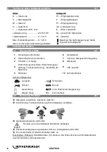
Overview:
1
Battery pack
4
Warning display
2
Sliding seat
5
Capacity indicator button
3
Operation display
6
Capacity and signal indicator
Start of operation
Before plugging in, check to see that the rated mains voltage and mains fre-
quency, as specified on the rating label, match your power supply.
Devices such as this one, which generate direct current, may have an effect on basic residual-
current circuit breakers. Use type F or better, with a release current of max. 30 mA.
Before commissioning the charger, ensure that the air slots are free. Minimum
distance to other objects is 5 cm.
Self-test:
Insert mains supply plug.
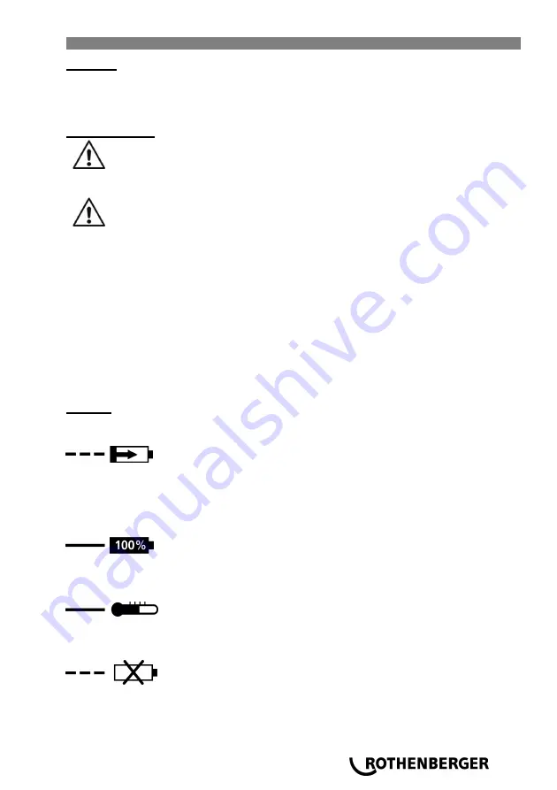
The warning display (4) and the operating indicator (3) light up one after the other for approx. 1
second and the installed fan runs for approx. 5 seconds.
Battery pack:
Charge the battery pack before use (1).
If performance diminishes, recharge the battery pack.
The ideal storage temperature is between 10°C and 30°C. The permissible storage temperature
is between 0°C and 50°C.
Li-ion battery packs
have a capacity and signal indicator: (6)
Press the button (5), the LEDs indicate the charge level.
If one LED is flashing, the battery pack is almost flat and must be recharged.
Handling
Charging battery pack:
Push the battery pack completely to the stop on the sliding seat (2).
The operating indicator (3) flashes.
Conservation charge:
Once the charging process has finished, the battery charger automatically switches to conserva-
tion mode.
The battery pack can remain in the battery charger and is therefore always ready for use.
The operating display (3) lights up continuously.
Fault:
●
Warning display (4) lights up continuously.
Battery pack is not charged. Temperature too high/ too low. When the temperature of the battery
pack is between 0 °C and 50 °C, the charging process begins automatically.
●
Warning display (4) flashes.
Battery pack is defective. Remove the battery pack immediately from the charger.
The battery pack was not pushed correctly onto the sliding seat (2).
Summary of Contents for RO DD60
Page 2: ...Overview RO DD60 B A Operating RO DD60 3 1 1 2 3 2 4 1 Nm Nm max Nm 1 2 3 4 6 9 10 5 8 7 ...
Page 157: ...NOTES ...
Page 158: ...NOTES ...
Page 159: ...NOTES ...


