16
ENGLISH
3.4
Removal of the tube blockage
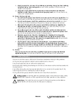
The screw should bore into the blockage and should not be pressed into the blockage!
Î
Should any counterpressure (resistance from the blockage) be felt then put the feed handle
into the neutral position (screw continues to revolve) until the counter pressure has
reduced.
Î
Set the feed handle on forwards until the counterpressure from the blockage is detected
again and then release once more.
Î
Repeat this process until the blockage has been removed.
During the tube cleaning the operating mode can be altered at any time as required.
If any increasing pressure build up on the screw is felt (recognisable by bending of the guide
hose
(6)
) then immediately switch to reverse feed!
Never release the pressure
transducer!
At any overload the motor is automatically switched off and the error display flashes (scrubbing
and smooth LED’s flash alternately).
If much of their elevated spirals in the roughing mode control switch off the engine, it should be
changed to account for losses in the spiral tube to compress into demModus pulses or silt.
Î
Reduce the overload by lightly pulling back the guide hose and then, after the drum has
come to a standstill, press the RESET button, select the required operating mode and
continue working.
Should the existing screw length not be sufficient then a second screw (
∅
16 x 15m, item no
7.2918) can be attached to the end of the screw.
3.5
Removal of the screw from the tube
Î
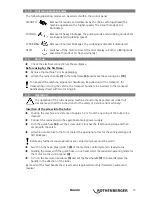
After completed removal of the blockage put the feed handle into reverse in order to pull
the screw back into the drum.
Ensure that the screw reverts effortlessly into the drum. Should the reverse become heavy and
difficult let the screw run back a little into the tube. Do not pull back the screw with force!
Î
During the reverse movement of the screw out of the tube place a water hose into the
opening of the tube and wash down the dirty screw with water. The unblocked tube will
also be washed out during this process.
Î
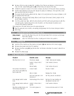
As soon as the attached tool is visible again put the feed handle into neutral position,
switch off the motor via the reset button or green switch
(8)
and remove the tool with
guide hose.
Î
Switch on the motor again and run the screw back until it protrudes approx. 20 cm from
the feed.
The screw must never be drawn completely back into the drum!
If the machine is being run with an extension screw this should, after removal from the tube, be
pulled back with the feed (in reverse drive) into the drum and uncoupled.
3.6
Extension of the working area by attaching a further screw
Attachment of the extension screw
Î
Switch off the motor when the full feed has been completed (the feed handle becomes
easily movable and the screw end piece is positioned in front of the feed)
Î
Release the guide hose and push it in the direction of the tube to the point where the quick
release coupling is accessible.
Summary of Contents for Rospeed 3F
Page 2: ...1 Overview A Maintenance B 12 12 10 1 3 2 2 11 6 5 9 8 7 4 ...
Page 3: ...Operating 1 3 2 3 4 5 ...
Page 4: ... i Operating ...
Page 104: ...100 NOTES ...
Page 105: ...101 NOTES ...
Page 106: ...102 NOTES ...
Page 107: ...103 NOTES ...


