RFD OPERATOR MANUAL
8-39
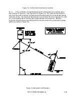
Figure 8-1 Unit Normal Transmission Location.
8.1.2.
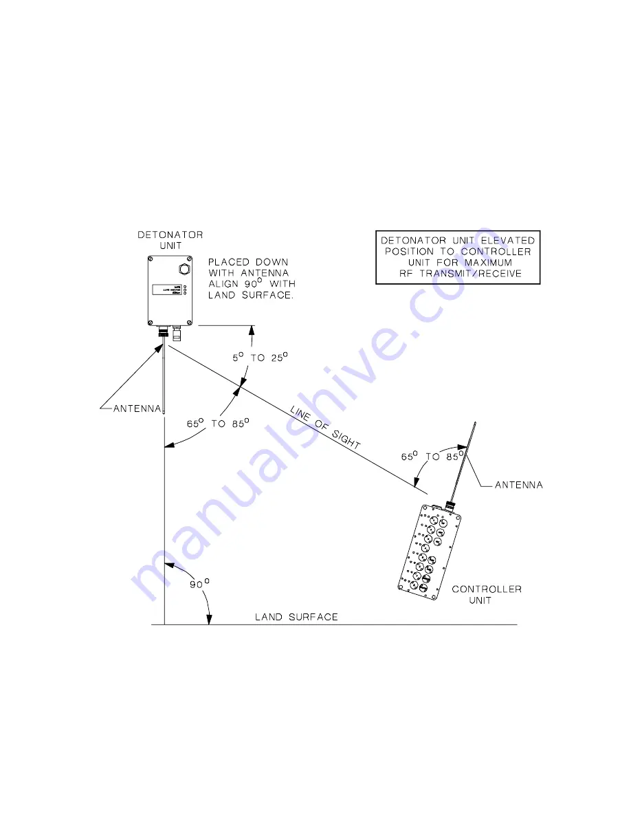
If the Controller unit and Detonator Unit must be placed in a position other
than location in Figure 8-1, use Figure 8-2 or Figure 8-3. The minimum transmission
will occur when the Controller Unit antenna and the Detonator Unit antenna are placed
in the line of site. The maximum transmission occurs when the line of site lays in a path
of 5 to 25 degrees above Unit top plane perpendicular to the antenna. Both the
Controller Unit antenna and the Detonator Unit Antenna have the same radiant energy
pattern as shown in Figure 8-4.
Figure 8-2 Detonator Unit Elevated.
Summary of Contents for REMOTE FIRING DEVICE
Page 6: ...RFD OPERATOR MANUAL vi ...
Page 12: ...RFD OPERATOR MANUAL 1 3 Figure 1 1 RFD System ...
Page 15: ...RFD OPERATOR MANUAL 2 6 Figure 2 1 RFD System ...
Page 27: ...RFD OPERATOR MANUAL 2 18 Figure 2 9 Detonator Antenna Battery Charger Connection ...
Page 49: ...RFD OPERATOR MANUAL 8 40 Figure 8 3 Detonator Unit Tilted ...
Page 50: ...RFD OPERATOR MANUAL 8 41 Figure 8 4 Antenna Radiation Pattern ...


