background image

-7-

-6-

Operating Instructions

Disconnect the plug from the
power source before making

any assembly, adjustments or changing
accessories.  Such preventive safety measures
reduce the risk of starting the tool accidentally. 

Slide "ON/OFF" Switch

This tool is switched "ON" by the slide switch
located on the front of the motor housing.

TO TURN THE TOOL "ON" slide the switch
button up.

TO TURN THE TOOL "OFF" slide the switch
button down or "0" position.

Hold the tool with both hands
while starting, since torque of

the motor can cause the tool to twist.

Installing Zip® Bits

The Zip Bits are held by a collet system.  At the
time your tool was assembled, the 1/8" collet
(used for 1/8" Zip Bits) was installed for your
convenience.  A 1/4" collet is required for 
1/4” inch diameter Zip Bits, sold separately.

Do not use .118" shank bits in the 1/8" collet,
use only Roto Zip Tool Corporation 1/8" Zip Bits.

Identify the different parts of your Zip Bits.

The Zip Bit flutes are sharp
and should be handled with

caution.

Step 1:
To insert a Zip Bit into the tool, first remove the
standard equipment wrench and locate the shaft
lock button.  Depress and hold down the shaft
lock button with one hand and at the same time
loosen the collet nut with the other hand by
turning it counter clockwise with the wrench for
a couple rotations.

Remove the old Zip Bit (if there is one), insert
shank of Zip Bit into the collet so that 1/16" to
1/8" of smooth shank remains visible above the
collet.

Do not allow the flutes/cutting
edges of the Zip Bit to fall into

the collet, and do not tighten the collet around
the flutes; doing so will result in broken Zip Bits.

After properly placing the bit into the collet,
depress the shaft lock button and
simultaneously tighten the collet nut in a
clockwise direction- first by hand and then with
the wrench until Zip Bit is held securely.  Be
careful to not overtighten the collet nut when
using the wrench. Doing so will make the collet
hole smaller, preventing you from inserting Zip
Bits in the future.

Changing the collet

As stated above, the 1/8" collet is used with 1/8"
diameter Zip Bits and the 1/4" collet is used with
1/4" diameter Zip Bits.  To interchange collets,
first remove the Zip Bit. Continue to loosen and
unscrew the collet nut until you can remove it
from the tool.  Remove the collet and replace it
with another.  (Each collet is double-ended, and
either end is acceptable to use.)  By hand, re-
tighten the collet nut around the collet in a
clockwise direction.  You are now ready to
insert a new Zip Bit as instructed in step 1
above.

!

WARNING

!

WARNING

DURING STORAGE of your
tool when there is no Zip Bit

in the collet, DO NOT tighten the collet nut
down onto an empty collet.  Doing so will make
the collet hole smaller, preventing you from
inserting Zip Bits into it in the future.

Adjusting, removing and installing the

depth guide assembly. 

(RTM01 & SCS01 models only)

Step 2:
Use the depth guide to adjust the depth of the
cut. The depth guide assembly consists of the
depth guide, locking knob and bracket. Loosen
(counter clockwise) the knob enough to enable
the depth guide to slide up or down to the
desired depth of your cut and re-tighten the
knob in a clockwise
direction.  It’s best
to set the guide at
about 1/8" greater
than the material
thickness.  For
example, to cut
1/2" plywood, set
the bit end so it
protrudes 5/8"
below the base
guide.  

Note: Zip Bits can cut materials up to 1" thick.  

In order to remove the depth guide, twist the
entire assembly,  approximately 1/8 of a turn, in
a counter clockwise fashion.  Pull the whole
assembly straight off the tool.  To re-attach the
assembly, align the notched areas of the depth
guide bracket up to the indentations of the tool
collar.  The depth guide assembly should easily
fall into place on top of the tool collar, and the
tops should be flush with one another.  Twist
the assembly clockwise about 1/8 of a turn until
the spring locks in place. 

Pro Series Classic Depth Guide assembly.

Locate the base
plate and its
locking screw.
Using the end of
the standard
wrench, loosen
( c o u n t e r
clockwise) the
screw enough to enable the base plate to slide
up or down to the desired depth of cut.  For best
performance, set the base plate so the Zip Bit
protrudes approximately 1/8" beyond the
material being cut.  For example, to cut a piece
of 1/2" thick plywood, set the base plate so the
Zip Bit protrudes 5/8" below the  base plate, as
shown here.  Re-tighten the screw in a
clockwise direction. 

Removing Depth Guide Assembly From Tool

and Reinstalling

In order to
remove the
depth guide
from the tool,
release the
locking lever
and pull the
entire assembly straight off of the tool.  To
reattach the assembly, fully replace the guide
onto the tool collar and lock the clamp lever.

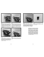
Make A Few Practice Cuts

After assembling the Zip Bit into the tool and
adjusting your depth guide, as described above,
you should make a few practice cuts with the
tool before attempting an actual job.

A few exercises will give you the necessary
practice to make clean, professional cuts.

Step 3:
Make certain that the collet nut is securely
tightened before turning the tool on.

Step 4:
Hold the Spiral Saw power tool firmly and turn
the tool ON.

Hold the tool with both hands
while starting, since torque

from the motor can cause the tool to twist.

Step 5:
While holding the tool firmly, insert the bit into
the material at a 45° angle.

!

CAUTION

!

WARNING

!

WARNING

SYSTEM COMPLETE

COLLET

NUT

COLLET 

SYSTEM SEPERATED

!

CAUTION

Summary of Contents for pro series classic

Page 1: ... s Manual Manuel de l utilisateur Manual del usuario Pro Series Classic Spiral SawTM Power Tool IMPORTANT Read Before Using IMPORTANT Lire avant usage IMPORTANTE Leer antes de usar Parlez vous français Voir page 13 Habla español Ver página 24 2002 Roto Zip Tool Corporation May be protected by one or more of the following U S Patents 5 143 490 5 323 823 5 813 805 5 902 080 6 048 260 D439 122 and D4...

Page 2: ... are easier to control Check for misalignment or binding of moving parts breakage of parts and any other condition that may affect the tools operation If damaged have the tool serviced before using Many accidents are caused by poorly maintained tools Develop a periodic maintenance schedule for your tool Use only accessories that are recommended by the manufacturer for your model Accessories that m...

Page 3: ...es per second W Watt Power kg Kilograms Weight min Minutes Time s Seconds Time Diameter Size of drill bits grinding wheels etc n0 No load speed Rotational speed at no load min Revolutions or reciprocation per minute Revolutions strokes surface speed orbits etc per minute 0 Off position Zero speed zero torque 1 2 3 Selector settings Speed torque or position settings I II III Higher number means gre...

Page 4: ...e collet DO NOT tighten the collet nut down onto an empty collet Doing so will make the collet hole smaller preventing you from inserting Zip Bits into it in the future Adjusting removing and installing the depth guide assembly RTM01 SCS01 models only Step 2 Use the depth guide to adjust the depth of the cut The depth guide assembly consists of the depth guide locking knob and bracket Loosen count...

Page 5: ...aterials EXCEPT cutting around outlet boxes in drywall steer the tool in a clockwise direction with slow steady pressure to make the cut Step 7 After completing your cut turn off the tool and carefully remove it from the material When cutting around outlet boxes in drywall use the Illustrated Instructions for Perfect Outlet Openings In Drywall section in this manual Do not attempt to use this tool...

Page 6: ... advantage of the hugging action of the rotating Zip Bit along the contours of the template Remember to use a smooth continuous motion 10 Step 5 Pull the Zip Bit out far enough to slip it over the edge of the box so it is now against the outside of the box Step 6 While keeping the Zip Bit in contact with the outside of the box move the tool counter clockwise while applying light inward and upward ...

Page 7: ...cher un outil dont l interrupteur est en position MARCHE peut mener tout droit à un accident Enlevez les clés de réglage ou de serrage avant de démarrer l outil Une clé laissée dans une pièce tournante de l outil peut provoquer des blessures Ne vous penchez pas trop en avant Maintenez un bon appui et restez en équilibre entout temps Un bonne stabilité vous permet de mieux réagir à une situation in...

Page 8: ...ours travailler en opposition c est à dire faire avancer l outil dans le matériau dans la direction du bord tranchant lorsque celui ci quitte le matériau ce qui est aussi le sens d évacuation des copeaux REMARQUE Les coupes intérieures et extérieures nécessiteront des sens de déplacement différents référez vous à la section consacrée au sens de déplacement de la toupie Si l outil est introduit dan...

Page 9: ...ez pas les Forets Zip à tige de 0 118 po dans la douille de 3 mm utilisez uniquement les Forets Zip Roto Zip Tool Corporation de 3 mm po Identifiez les différentes pièces de vos mèches Les cannelures des Forets Zip sont vives et doivent être maniées soigneusement Étape 1 Pour insérer une Foret Zip dans l outil retirez d abord la clé de serrage standard et repérez le bouton de blocage de l arbre En...

Page 10: ...ur désirée de votre coupe et resserrez le bouton en sens horaire Il est préférable de régler le guide à environ 3 mm de plus que l épaisseur du matériau Ainsi pour couper du contreplaqué de 13 mm placez l extrémité de la Foret Zip de manière à ce qu elle fasse saillie de 16 mm sous le guide de la base Remarque Les Forets Zip peuvent couper des matériaux allant jusqu à 25 mm d épais Pour déposer le...

Page 11: ...ut en exerçant une légère pression continue vers la boîte 20 Étape 1 Assurez vous que les fils électriques sont poussés vers l arrière ou le côté éloigné de la boîte de manière à ce que le Foret Zip ne coupe pas les fils lorsqu il est inséré à travers le mur sec Le Foret Zip de votre marteau constitue un excellent outil à cette fin Étape 2 Avant de fixer la plaque vous devez faire une marque à pro...

Page 12: ...endredi entre 8 et 16h30 heure normale du centre au 1 877 768 6947 sans frais aux États Unis ou au Canada ou au 608 798 6577 Intensité nominale de l outil Longueur en pieds Longueur en mètres 3 6 6 8 8 10 10 12 12 16 18 16 16 14 75 75 1 5 2 5 18 16 14 12 75 1 0 2 5 4 0 18 16 14 12 75 1 0 2 5 4 0 16 16 14 12 1 0 2 5 4 0 14 12 25 50 100 150 15 30 60 120 Calibre A W G Calibre en mm2 AVERTISSEMENT For...

Page 13: ...ntenga un apoyo de los pies y un equilibrio adecuados en todo momento El apoyo de los pies y el equilibrio adecuados permiten un mejor control de la herramienta en situaciones inesperadas Utilice equipo de seguridad Use siempre protección de los ojos Se debe utilizar una máscara antipolvo zapatos de seguridad antideslizantes casco o protección de los oídos según lo requieran las condiciones Utiliz...

Page 14: ...ocidad aumenta desde la apagado graduación de 0 Flecha Acción en la dirección de la flecha Corriente alterna Tipo o una característica de corriente Corriente continua Tipo o una característica de corriente Corriente alterna o continua Tipo o una característica de corriente Construcción de clase II Designa las herramientas de construcción con aislamiento doble Terminal de toma de tierra Terminal de...

Page 15: ...UERCA DEL PORTAHERRAMIENTA PORTAHERRAMIENTA SISTEMA SEPARADO PRECAUCION ADVERTENCIA 28 Instrucciones de funcionamiento Desconecte el enchufe de la fuente de energía antes de realizar cualquier ensamblaje o ajuste o cambiar accesorios Estas medidas de seguridad preventivas reducen el riesgo de arrancar la herramienta accidentalmente Interruptor corredizo ON OFF de encendido y apagado Esta herramien...

Page 16: ...endrá Tanto una presión excesiva como un corte rápido generan un calor excesivo y pueden acortar la duración de la broca NOTA Al cortar en una superficie vertical evite terminar el corte en la parte inferior del agujero Si es posible empiece y termine el corte en la parte superior para que la pieza de desecho no caiga sobre la broca Zip que gira Apague la herramienta y retírela del material 30 31 ...

Page 17: ...el resultado será un corte de abertura dañado Recuerde usar un movimiento suave y continuo Paso 5 Saque la broca Zip sólo lo suficiente para deslizarla sobre el borde de la caja de modo que ahora la broca Zip se encuentre contra la parte exterior de la caja No es necesario que tire de la broca Zip hasta sacarla completamente de la pared de tipo seco Al llegar a este punto debe convertirse en artis...

Page 18: ...vitar accidentes desconecte siempre la herra mienta de la fuente de energía antes de la limpieza o de la realización de cualquier mantenimiento La herramienta se puede limpiar más eficazmente con aire comprimido seco Use gafas de seguridad siempre que limpie herramientas con aire comprimido Las aberturas de ventilación y las palancas de interruptor deben mantenerse limpias y libres de materias ext...

Page 19: ...is defective and has not been misused carelessly handled or defaced by repairs made or attempted by others This warranty does not apply to accessories This warranty gives you specific legal rights and you may also have other rights which vary from state to state This warranty applies only to Roto Zip Tool Corporation tools sold within the United States of America Canada and the Commonwealth of Pue...

Reviews: