2
.
August 2019
.
IMO_66_EN_v2 / 104674
Roto Safe E601 – Eneo AF
Subject to change.
SHC
BS
CGC
RW 16
RW 16
RW 16
Connection for
Eneo Control Unit!
Power supply unit:
installation in
switch cabinet
OUTSIDE
INSIDE
Flush-mounted box
Flush-mounted box
(System 2001, 530715)
DoorMan
Access
system
or
Surface-
mounted
installation
DoorMan
reading device
recommended
installation height
1350 mm
Power
supply
lines
Dimensions
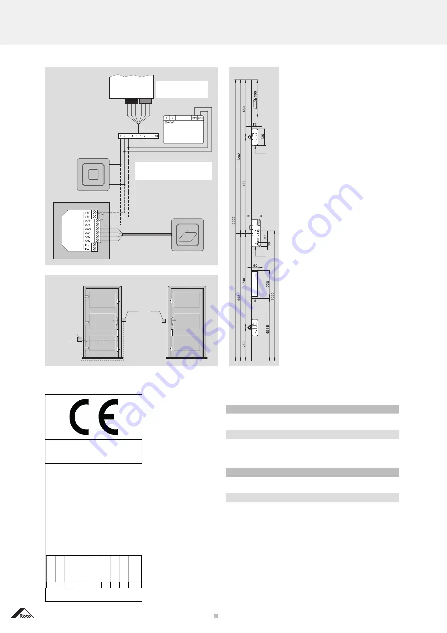
Wiring diagram, dimensions, installation instructions, cables, CE
Roto Safe Eneo AF
GND
+24V
IN1
Brown
White
Yellow
Green
Power
supply
Relay-
output
DoorMan
read head
Time-con-
trolled input
DoorMan access system (optional)
Outside: DoorMan
read head
Power supply unit
Mat. no. 563 512
Brown
Green
White
White
Brown
Inside:
Push-button
switch: ‘Unlock
door’
Green
Brown
Eneo 3 pin plug
Green Bro
wn
W
hite
Eneo 10 pin plug from the
plug-in cable junction
Mat. no. 494 799
Connector pin assignment
Terminal 1
... Description: IN1 / Input 1 (OPEN)
Terminal 2
... Description: +24 V
Terminal 3
... Description: GND
BLACK
GREEN
Wiring diagram
Cable assignment
White:
IN1 / Input 1 (OPEN)
Brown: +24V
Green:
GND
W
hite
Bro
wn
Green
Installation instructions
The ‘automatic function’ (spring-loaded)
is only ensured in the vertical position.
Door commissioning:
Prior to con-
necting up the Roto Safe Eneo AF to
the power supply, test the Roto Safe
Eneo AF’s operation manually. The ef-
fort needed to activate the lever-handle
may not exceed the normal manual
force.
Checking the door has been in-
stalled correctly:
Check as to whether
the sash meets the frame and check
the hardware and locking parts’ smooth
operation. Check the functional clear-
ance (4–5 mm). Manually check the
closing and opening function via both
the lever-handle and the key while the
power is switched off.
Roto Safe Eneo AF requires lever-
handle versions with split spindle (pull
handle or similar on the outside,
lever-handle on the inside).
Position the lever-handle height at
between 900 mm and 1100 mm. The
installation company bears all responsi-
bility for any deviations.
CE marking and classification key explanatory com
-
ments in accordance with the DIN EN 179 standard
0757
Roto-Frank Austria GmbH
Lapp-Finze-Str. 21
A-8401 Kalsdorf bei Graz
Austria
Notausgangsverschluss lt. EN179 – P603
LE/DoP-Nr. :
KD/Door/E601/Nr. 002/CPR/2013-05-15
13
EN 179:2008-04
Notausgangsverschluss mit Drückerbetätigung,
Typ A für Türen in Rettungswegen,
für außen und innen öffnende Türen
n
e
d
n
a
t
s
e
b
e
b
a
g
i
e
r
F
r
u
z
t
i
e
k
g
i
h
ä
F
(≤
1sec)
(W
≤
100mm)
(A≤7
0N)
Dauerfunktionstüchtigkeit
hinsichtlich der Fähigkeit zur
Freigabe gegenüber Alterung und
Qualitätsverlust
(von Türen in Fluchtwegen)
Kontrolle gefährlicher Stoffe
bestanden
(96h)
(100 000Zyklen)
bestanden
N
ut
zun
g
s-
ka
te
go
rie
D
aue
rf
un
kt
io
n
M
as
se
T
ür
Fe
ue
r-
/
R
au
ch
sc
hu
tz
S
ic
he
rhe
it
K
orr
os
io
ns
ve
rha
l
te
n
S
ic
he
rhe
it
E
inb
ru
ch
sc
hu
tz
Ü
be
rs
tan
d
de
s
B
esc
hl
ag
s
B
et
ät
ig
ung
sa
rt
A
nw
en
d
ung
sb
er
ei
ch
3
6
5
0
1
3
2
2
A
B/D
Zertifikat zur Bescheinigung der Leistungsbeständigkeit
Nr. 0757-CPR-229PANIK-7031575-2 erstellt durch
ift Rosenheim NB-Nr. 0757
Maximum cable lengths
...when using Eneo 180° plug-in cable junctions, (mat. no.
494799) to the power supply unit.
From the connector strip in the Eneo cable junction
up to 4 m
up to 10
m
up to 20
m
up to 30
m
up to 50
m
0,34 mm²
0,75 mm
²
1 mm²
1,5 mm²
2,5 mm²
...when using Eneo 180° opening cable junctions, non plug-
in (mat. no. 319135), with cable for cable junction 7x0.5
mm
2
, 10 m. (mat. no.
348564)
From the Eneo drive unit
up to 10
m
up to 20
m
up to 30
m
up to 50
m
0,5 mm²
1 mm²
1,5 mm²
2,5 mm²


