10
Installation & Maintenance
Instructions
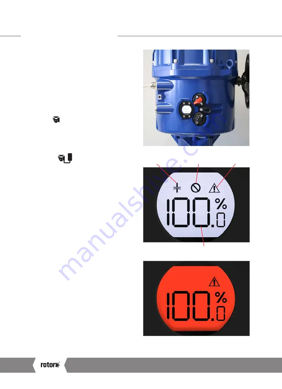
Critical Fault
Non Critical Fault
Position Status
RPP Status
5.1 Outside the Actuator
5.1.1 Local Controls & External LCD Display
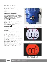
Actuators are supplied with local controls and an external
backlit display.
Selecting Local/Stop/Remote Operation
The red and black selector determines operating mode as
LOCAL, STOP or REMOTE. This can be locked in place with a
6.5mm hasp padlock. STOP remains available when the unit
is locked in LOCAL or REMOTE. LOCAL or REMOTE is not
available when the unit is locked in STOP.
Local Control
In LOCAL mode, the black selector can be rotated for Open
or Close operation.
Actuator operation can be configured for Push-to-Run or
Self-Maintained. Refer to section 11.2.5.
Remote Control
In REMOTE mode, the actuator will respond to configured
remote control signals. Refer to section 11.2.5.
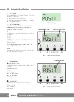
Status Display
The external LCD display shows position and fault status of
the actuator. Charge status is also shown when RPP is fitted.
5.1.2 Reserve Power Pack (RPP)
The optional RPP stores electrical energy with super
capacitors so that a preconfigured power loss action is
performed on power failure.
Charging of the super capacitors will only take place with the
top cover fitted.
Electrical operation is inhibited during the initial charging
period. Charging can take up to 5 minutes.
When power is lost, the actuator will perform the configured
fail to position action. The external LCD display will alternately
flash red and white whilst the RPP is discharging. The RPP can
take up to 15 minutes to fully discharge.
Fig 5.1
External view of actuator
Fig 5.2
Positional display
Fig 5.3
Actuator flashes Red and White
alternately when power failure occurs
5.0 Actuator Identification
A4
US
US
A4
US
A4
US
A4

