14
Installation & Maintenance
Instructions
6.2 Mounting the Actuator
CAUTION
It is essential that the actuator mounting procedure
is carried out when the valve is not under working
process conditions, as full valve movement may occur.
IMPORTANT
It is essential that the actuator is mounted correctly to
the valve.
The height of the yoke or pillar and mounting plate, in
relation to the top of the valve spindle is critical to ensure full
stroke movement of the valve.
The Installation & Setup will include the following procedures:
1. Ensure valve is closed and safe (offline)
2. Actuator output shaft is retracted
3. Mount and align actuator to valve
4. Carry out basic setup
WARNING
The actuator can weigh up to 50 Kg (110 lbs). It is
necessary to lift the actuator using mechanical lifting
equipment, certified slings and shackles must be
attached to the lifting eyes provided. Trained and
experienced personnel should ensure safe lifting
practices at all times.
DO NOT LIFT THE ACTUATOR AND VALVE
COMBINATION VIA THE ACTUATOR. ALWAYS LIFT THE
VALVE / ACTUATOR ASSEMBLY VIA THE VALVE.
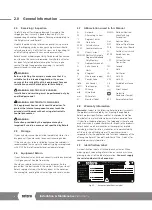
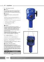
6.2.1 Handwheel Operation
The handwheel is located on the side of the CMA.
The handwheel is always available to be operated.
When the actuator is commanded to move electrically, the
handwheel can still be safely operated, but it will affect the
speed or direction of the output drive.
Verify direction of output shaft rotation for clockwise
operation of the handwheel.
WARNING:
OPERATING BY HAND
Note that under no circumstances should any
additional lever device such as a wheel key or wrench
be applied to the hand-wheel in order to develop more
force when closing or opening the valve as this may
cause damage to the valve and/or actuator. It may also
cause the valve to become stuck in the seated or back
seated position.
Model
Output When Hand Wheel
is Turned Clockwise
CMA - Linear
CML-1500/3000
Extend
Table 1
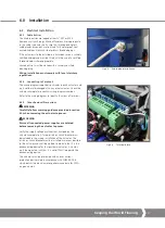
Fig 6.1
CML-3000
6.0 Installation
A4
US
US
A4
US
A4
US
A4

