20
Installation & Maintenance
Instructions
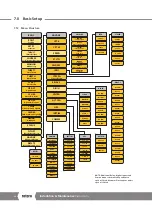
7.0 Basic Setup
7.1
Basic Setup
Basic setup is required once the actuator has been mounted
on to the valve.
Procedures include:
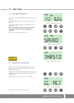
Step 1 Select Local Operation
Step 2 Set Output Thrust
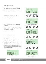
Step 3 Select Action at End of Travel ( Limit or Force)
Step 4 Set Close Limit of Travel
Step 5 Set Open Limit of Travel
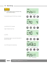
Step 6 Calibrate Command Signal Zero Setpoint
Step 7 Calibrate Command Signal Span Setpoint
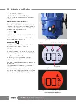
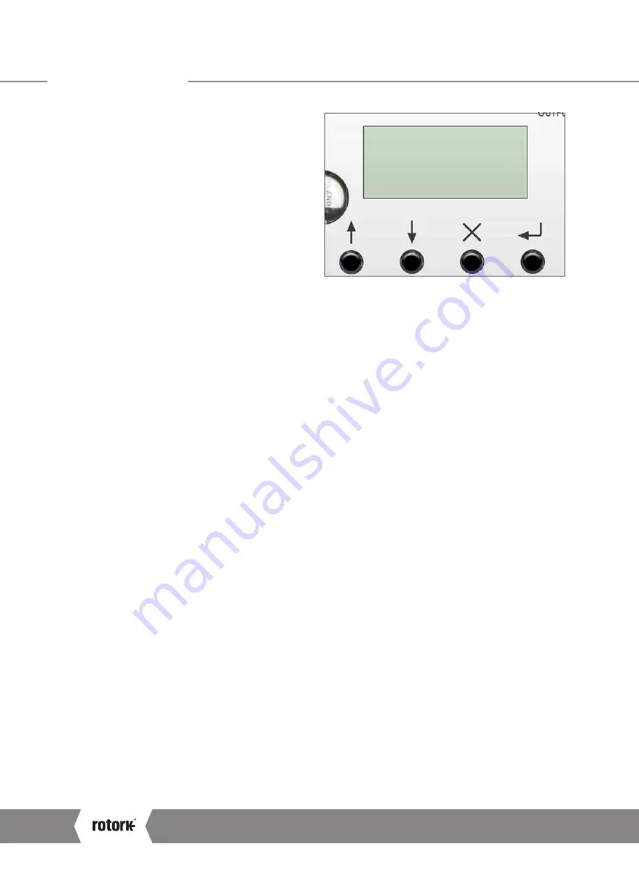
The Basic Setup procedure is performed by using the 4
push buttons mounted below the LCD display on the
user interface.
Actuator must be set to LOCAL with the Local/Stop/
Remote selector to change configuration parameters.
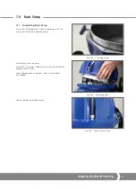
Power supply must be restored to perform setup of the
actuator. Power supply should only be restored once
the cover is safely removed (refer to section 6.3.3).
Charging of the Reserve Power Pack (RPP) is prevented
whilst the top cover is removed. This is prevented with
an automatic switch to reduce the risk of electrical
shock during setup.
The power loss action is also disabled whilst the
actuator top cover is removed as the RPP will not
contain any charge.
Changing control mode to STOP or REMOTE when
editing a configuration parameter will cancel the
setting change and return the setting to the last
saved value.
UP
DOWN
CANCEL
ENTER
POS I T
LOCAL
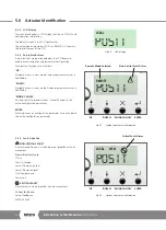
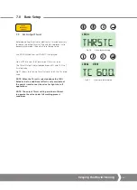
Fig 7.1
Default display
A4
US
US
A4
US
A4
US
A4

