50
Installation & Maintenance
Instructions
11.0 Advanced Menu
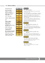
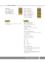
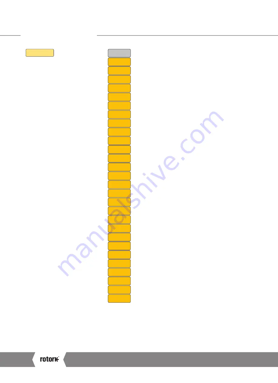
COMMS
MOD BD
MOD AD
MOD PR
MOD TM
MOD 2A
MOD FT
PRO FT
PRO RP
PRO RM
PRO T1
PRO T2
PRO AD
GSD AC
PAK BD
HRT AD
HRT DS
FFB FT
PAK AD
DEV AD
F RANG
FCAL L
FCAL H
COM TO
DEV BD
LOS ACT
LOS POS
MIN SP
MAX SP
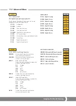
COMMS
11.2.14 COMMS - Bus Option Card
Configuration
The following menus appear automatically
when a Bus Option Card is fitted.
For full details of each Bus Option Card and
its menu settings please refer to the relevant
technical manual.
MODBUS
MODBD
Modbus BaudRate
MODFT
Modbus Field Type
MODAD
Modbus Address
MODPR
Modbus Parity
MODTM
Modbus Termination
MOD2A
Modbus Second Address
PROFIBUS
PROFT
Profibus Field Type
PROAD
Profibus Address
PRORT
Profibus Redundancy Type
PRORM
Profibus Redundancy Mode
PROT1
Profibus Termination1
PROT2
Profibus Termination2
GSDAC
Profibus GSD Active
Characterisation Active
PAKSCAN
PAKAD
Pakscan Address
PAKBD
Pakscan Baud Rate
HART
HRTAD
Hart Address
HRTDS
Hart Demand Source
FOUNDATION FIELDBUS
FFB FT
Foundation Fieldbus Type
DEVICENET
DEVAD
DeviceNet Address
DEVBD
DeviceNet Baud Rate
FOLOMATIC
F RANGE
Select mA or voltage (5 V or 10 V)
type signal
FCAL L
Calibrate Low signal setpoint
Apply low input analogue signal
and save setting
FCAL H
Calibrate High signal setpoint
Apply High input analogue signal
and save setting
To apply changes the actuator must be set to
"LOCAL" operation and in "EDIT" mode.
Save to confirm changes.
STANDARD PARAMETERS (ALL BUS CARDS)
COMTO
Comms Time Out
LOSACT
Loss of Comms Action
LOSPOS
Loss of Comms Position
MINSP
Minimum Span
MAXSP
Maximum Span
A4
US
US
A4
US
A4
US
A4


