background image

Keeping the World Flowing

37

9.0  Fault History Menu

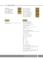
STALL TIME

CPT 20

CMD SRCE

CPT 4

INFO

SPLT RANGE

RELAYS

ACT CFG

ADVANCED

POSIT

Position

SET PT

Setpoint

THRUST or TORQUE

Thrust or Torque

LOCREM

Local / Remote Control

MANJOG

Manual Jog

CL LIM

Close Limit (zero)

OP LIM

Open Limit (span)

CFG

Control Setup

CMD4

Field Command Signal4

CMD20

Field Command Signal20

DBAND

Deadband

FLTHST

Fault History Access

ADVANC

Advanced Menu

DEFLTS

Default Menu Access

STATUS

BASIC

INFO

ACT STS

AMP STS

TEMP

SWR VER

CTR SETUP

CTRLAL

IN DMP

LOS TO

LOS ACT

LOS LOW

LOS HI

TORQ O

TORQ C

CL ACT

OP ACT

RELAYS

RLY1 CFG

RLY1 POS

RLY1 FRM

RLY2 CFG

RLY2 POS

RLY2 FRM

ACT CFG

ACT TYPE

ACT SIZE

ENCOD IN

ASRACT

SP RANGE

MIN CMD

MAX CMD

BSRACT

ST CUST

LD CUST

DEFAULTS

LD FACT

9.1  Fault History

Alarms and Faults are stored and listed by event number and 
type. Time intervals between events are indicated between 
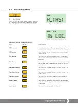
each event, Fig 9.2 shows event 16 is Local selected status.

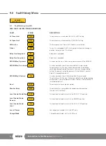
CMA FAULT HISTORY STRING DEFINITIONS

FAULT          

STRING 

DESCRIPTION

LOS Command 

CMD


Loss of Command Signal – The input command signal   


exceeded the range configure by the LOS LO and LOS HI parameters.

LOS Feedback 

FB


Loss of Feedback Position – An error has occurred in reading the  


feedback device.

Stall Opening 

STO


The actuator has been commanded to move in the open direction  


and has not done so for longer than the time limit set in STL TO   


parameter.  

Stall Closing 

STC


The actuator has been commanded to move in the closed direction  


and has not done so for longer than the time limit set in STL TO   


parameter.  

Over Thrust Opening 

OTH


The actuator has exceeded the Thrust Limit while running in the   


open direction.  

Over Thrust Closing 

CTH


The actuator has exceeded the Thrust Limit while running in the   


closed direction.  

Over Temperature 

OTP


The actuator’s current internal temperature has exceeded the    


maximum limit.

Loss of Comms 

COM


Communications between the actuator and its communications 


card has been lost for longer than the time specified in the COM  


TO parameter.

Local Control 

LOC


The actuator was configured for LOCAL control. 

LOCAL

FLTHST

LOCAL

%

 16  LOC

VIEW

Fig 9.1 

 Fault history menu

Fig 9.2 

 Event 16 showing LOCAL mode

A4

US

 US

 A4

 US

 A4

A4

US

Summary of Contents for CMA Series

Page 1: ...Linear Control Valve Actuators CMA Range CML1500 and CML3000 Installation Maintenance Instructions ...

Page 2: ...e Use FMC ATEX IECEx approved actuators 8 3 5 Certification Numbers 8 3 6 Safety Warnings 8 4 0 Health Safety 9 5 0 Actuator Identification 10 5 1 Outside the Actuator 10 5 2 Inside the Actuator 11 6 0 Installation 13 6 1 Installing your Actuator 13 6 2 Mounting the Actuator 14 6 3 Electrical Installation 17 7 0 Basic Setup 20 7 1 Basic Setup 20 7 2 Basic Menu Structure 21 7 3 Basic Setup Flowchar...

Page 3: ...arked on and supplied with the product Inform and educate personnel in the proper installation operation and maintenance of the product Install equipment as specified in Rotork installation instructions and per applicable local and national codes Connect all products to the proper electrical sources To ensure proper performance use qualified personnel to install operate update and maintain the uni...

Page 4: ...certification Any inspection or repair of Hazardous Area approved actuators should not be undertaken unless it conforms to National Legislation and Statutory Provisions relating to the specific Hazardous Area Only Rotork approved actuator replacement parts should be used Under no circumstances should any modification or alteration be carried out on the actuator as this could invalidate the conditi...

Page 5: ...lications requiring exact position control and continuous modulation Refer to Section 3 Approvals for further detail concerning approved actuators 2 3 1 CML Linear The CML range of actuators are high precision linear actuators capable of producing a modulating thrust from 100 to 3000 pounds force 13 35 kN depending on model size NOTE Thrust and Speed are dependent on frame size See PUB094 001 for ...

Page 6: ...ct your local Rotork representative or the factory direct at the adress on the nameplate quoting the actuator type and serial number 2 7 Abbreviations used in this Manual A Ampere AC Alternating Current C Degrees Celsius CW Clockwise ACW Anti clockwise CCW Counter clockwise DC Direct Current EEPROM Electrically Erasable Programmable Read Only Memory F Degrees Fahrenheit G Earth Ground Hz Hertz kg ...

Page 7: ...andard Temperature Low Temperature Option Directive 2014 34 EU II 2GD c 20 to 65 C 4 to 150 ºF 40 to 60 C 40 to 140 ºF Standard EN 60079 0 EN 60079 1 EN 60079 31 EN 13463 1 EN 13463 5 Ex db IIB T4 Gb Ex tb IIIC T85 C Db Units fitted with UPS or HMI option 20 to 60 C 4 to 140 ºF International Hazardous Area IECEx Directive Standard Rating Standard Temperature Low Temperature Option No Directive II ...

Page 8: ...0 27 9 3 3 Environmental Conditions a Altitude up to 5000 meters b CMA adheres to requirements consistent with Overvoltage Category II c The CMA adheres to the requirements consistent with a Pollution Degree of 2 3 5 Certification Numbers Canada FMC FM18CA0156X Europe ATEX FM17ATEX0012X International IEC IECEx FMG 17 0007X 3 6 Safety Warnings WARNING The screws securing the outer window frame main...

Page 9: ...n equipment must be worn when using this product WARNING LOCAL CONTROLS Selecting STOP position on the Local Stop Remote control knob does not guarantee that the actuator will lock in place ESD and the RPP power failure action can be configured to override STOP possibly resulting in actuator movement WARNING ENCLOSURE Screws securing the outer window frame maintain the integrity of the flame proof...

Page 10: ...he actuator will respond to configured remote control signals Refer to section 11 2 5 Status Display The external LCD display shows position and fault status of the actuator Charge status is also shown when RPP is fitted 5 1 2 Reserve Power Pack RPP The optional RPP stores electrical energy with super capacitors so that a preconfigured power loss action is performed on power failure Charging of th...

Page 11: ...ternal user interface The user interface comprises LCD display and push buttons Fig 5 4 Internal interface Fig 5 5 Terminal Block 5 2 2 Terminal Block Connections for the power control and indication wiring are provided by terminal blocks fitted to the top side of the electrical chassis Wiring must always use appropriate crimps and follow good wiring practices ...

Page 12: ...Navigate menus in view mode Increase parameter values in Edit Mode DOWN Navigate menus in view mode Decrease parameter values in Edit Mode MODE CANCEL Exit and return to previous menu Cancel changes to the active configuration parameter ENTER Enter sub menu or configuration parameter Save changes to the active configuration parameter 5 2 5 Fault Indication NON CRITICAL FAULT An alarm condition exi...

Page 13: ...rformance use only qualified personnel to install operate update and maintain the unit When replacement parts are required ensure that the qualified service technician uses only replacement parts specified by Rotork Substitutions will invalidate any hazardous area certification and may result in fire electrical shock other hazards or improper operation Keep all product protective covers in place e...

Page 14: ... provided Trained and experienced personnel should ensure safe lifting practices at all times DO NOT LIFT THE ACTUATOR AND VALVE COMBINATION VIA THE ACTUATOR ALWAYS LIFT THE VALVE ACTUATOR ASSEMBLY VIA THE VALVE 6 2 1 Handwheel Operation The handwheel is located on the side of the CMA The handwheel is always available to be operated When the actuator is commanded to move electrically the handwheel...

Page 15: ...ually operate the actuator using the handwheel to the retracted position to allow installation Push and turn the handwheel to retract the output shaft Valve Stem Coupling Machine the valve stem to actuator output shaft coupling adaptor to suit NOT SUPPLIED Fit the coupling to the valve stem It may be necessary to use a locking nut to eliminate any backlash Leave the coupling loose and free to rota...

Page 16: ...he valve stem If the actuator output shaft reaches its fully extended position it will be necessary to retract the actuator shaft a sufficient distance to allow adjustment of the coupling to ensure a tight shut off in thrust seating valves WARNING It is critical that there is correct alignment between the actuator output shaft and the valve stem Misalignment will result in increased mechanical wea...

Page 17: ...plate to confirm wiring diagram number Refer to the wiring diagram to identify functions of terminals 6 3 3 Cover Removal Precautions WARNING Carefully follow warning guidance provided in section 4 0 when removing the actuator top cover WARNING Ensure all connected power supplies are isolated before removing the actuator top cover Verify the supply voltage matches that stamped on the actuator name...

Page 18: ... Refer to Fig 6 10 6 3 5 Removing Top Cover Using a 8 mm Allen key loosen the captive fixings securing the top cover to the actuator body Do not attempt to lever off the cover with a screwdriver as this will damage the o ring seal and may damage the flamepath on a certified unit 4 set screws are provided to aid removal of the cover Refer to Fig 6 12 Fig 6 10 External protective earth Fig 6 11 Cove...

Page 19: ...llowing power supply voltages Single Phase 50 Hz 60 Hz 110 115 120 208 220 230 240 VAC DC 24 VDC Only Supply voltage fluctuations not to exceed 10 of the nominal supply voltage Supply frequency tolerance 10 6 3 7 Fuses The DC fuse is a 10 amp 250 volt type 3AG The AC fuse is a 5 amp fuse which is not serviceable Rated to supply 500 watts at 110 volts which is twice the output power of the supply 6...

Page 20: ... must be set to LOCAL with the Local Stop Remote selector to change configuration parameters Power supply must be restored to perform setup of the actuator Power supply should only be restored once the cover is safely removed refer to section 6 3 3 Charging of the Reserve Power Pack RPP is prevented whilst the top cover is removed This is prevented with an automatic switch to reduce the risk of el...

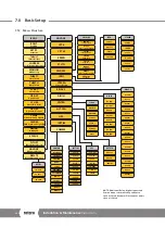
Page 21: ...vanced Menu DEFLTS Default Menu Access STATUS POSITION SETPOINT THRUST LOCAL REMOTE OPERATION MANJOG CLOSE THRUST OPEN THRUST CLOSE ACTION OPEN ACTION CLOSE LIM OPEN LIMIT FIELD COMMAND SIGNAL 4 FIELD COMMAND SIGNAL 20 DEADBAND STATUS FAULT HISTORY ADV MENU ACCESS DEFAULTS 7 0 Basic Setup 7 3 Basic Setup Flowchart STEP 1 SELECT LOCAL OPERATION STEP 2 SET OUTPUT THRUST STEP 4 SET CLOSE LIMIT OF TRA...

Page 22: ...F TRAVEL STEP 5 SET OPEN LIMIT OF TRAVEL STEP 6 CALIBRATE COMMAND SIGNAL ZERO SETPOINT STEP 7 CALIBRATE COMMAND SIGNAL SPAN SETPOINT STEP 3 SELECT ACTION AT END OF TRAVEL LIMIT OR FORCE STEP 8 DEADBAND POSIT REMOTE POSIT LOCAL Fig 7 2 Actuator in STOP Fig 7 3 Actuator in LOCAL Fig 7 4 REMOTE mode indication Fig 7 5 LOCAL mode indication Rotate the LOCAL STOP REMOTE selector anti clockwise until th...

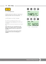
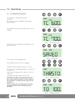
Page 23: ...rated value NOTE When the Thrust is selected above the 100 Rated value this additional effort is only available at the end of travel to seat the valve for tight shut off applications NOTE The output Thrust setting must be sufficient to operate the valve under full working process conditions STEP 1 SELECT LOCAL OPERATION STEP 2 SET OUTPUT THRUST STEP 4 SET CLOSE LIMIT OF TRAVEL STEP 5 SET OPEN LIMI...

Page 24: ...hrust Output is adjustable between 60 and 150 of its rated value Fig 7 12 shows the Opening Thrust value set to 100 of its rated value Press ENTER to change the Open Thrust set value NOTE When the Thrust is selected above the 100 Rated value this additional effort is only available at the end of travel to seat the valve for tight shut off applications NOTE The output Thrust setting must be suffici...

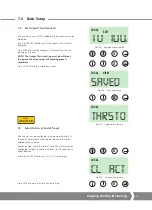
Page 25: ...es do not require thrust to be applied to the valve seat To provide tight shut off at end of travel the actuator can be configured to apply its configured thrust to the valve seat in either direction Use the UP DOWN buttons until CL ACT is displayed Press ENTER to view the Close Action setting X X LOCAL THRSTO LOCAL CL ACT X X LOCAL SAVED VIEW X LOCAL TO 100 EDIT STEP 1 SELECT LOCAL OPERATION STEP...

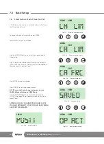
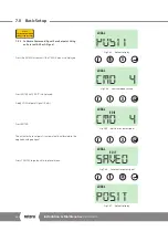
Page 26: ...f travel Press ENTER to save any changes Press CANCEL to return to previous menu NOTE Ensure that any changes to parameters are SAVED before returning to VIEW Mode Use the UP DOWN Buttons to select the Open Action OP ACT and repeat the procedure to select the Action at End of Travel AFTER SAVING ANY CHANGES PRESS CANCEL UNTIL YOU HAVE RETURNED TO THE TOP LEVEL BASIC MENU AND POSIT IS DISPLAYED LOC...

Page 27: ...SED End of Travel Limit is saved to the actuators memory THE CLOSED END OF TRAVEL LIMIT IS SET Press CANCEL to go back to top level menu LOCAL MANJOG X X X X EDIT LOCAL CL LIM LOCAL EDIT CL LIM LOCAL SAVED EDIT X X STEP 2 SET OUTPUT THRUST STEP 4 SET CLOSE LIMIT OF TRAVEL STEP 5 SET OPEN LIMIT OF TRAVEL STEP 6 CALIBRATE COMMAND SIGNAL ZERO SETPOINT STEP 7 CALIBRATE COMMAND SIGNAL SPAN SETPOINT STE...

Page 28: ...t drive to the required OPEN position Press ENTER and the new OPEN End of Travel Limit is saved to the actuators memory THE OPEN END OF TRAVEL LIMIT IS SET Press CANCEL to go back to top level menu STEP 4 SET CLOSE LIMIT OF TRAVEL STEP 5 SET OPEN LIMIT OF TRAVEL STEP 6 CALIBRATE COMMAND SIGNAL ZERO SETPOINT STEP 7 CALIBRATE COMMAND SIGNAL SPAN SETPOINT STEP 3 SELECT ACTION AT END OF TRAVEL LIMIT O...

Page 29: ...rrent A signal derived from the actuator position feedback is compared with a signal proportional to the input signal The difference error is used to energize the motor and drive the output to the required position to cancel the error Unwanted frequent operation can be prevented by adjustment of the deadband NOTE The 4 mA command signal is automatically referenced to the fully closed limit positio...

Page 30: ...isplayed Apply LOW setpoint signal 4 mA Press ENTER The actuator Zero setpoint is automatically calibrated to the applied analogue signal Press CANCEL to go back to top level menu STEP 4 SET CLOSE LIMIT OF TRAVEL STEP 5 SET OPEN LIMIT OF TRAVEL STEP 6 CALIBRATE COMMAND SIGNAL ZERO SETPOINT STEP 7 CALIBRATE COMMAND SIGNAL SPAN SETPOINT STEP 8 DEADBAND Fig 7 33 Default display Fig 7 34 Low command s...

Page 31: ... EDIT is displayed Apply HIGH setpoint signal 20 mA Press ENTER The actuator SPAN setpoint is automatically calibrated to the applied analogue signal Press CANCEL to go back to top level menu STEP 5 SET OPEN LIMIT OF TRAVEL STEP 6 CALIBRATE COMMAND SIGNAL ZERO SETPOINT STEP 7 CALIBRATE COMMAND SIGNAL SPAN SETPOINT STEP 8 DEADBAND Fig 7 38 Default display Fig 7 39 High command setting Fig 7 40 Edit...

Page 32: ...ed control response It may be necessary to increase the deadband if the actuator Hunts or overshoots the command setpoint giving spurious operation Press ENTER to save the current Deadband Value Press CANCEL to go back to top level menu STEP 6 CALIBRATE COMMAND SIGNAL ZERO SETPOINT STEP 7 CALIBRATE COMMAND SIGNAL SPAN SETPOINT STEP 8 DEADBAND LOCAL DBAND X X X X EDIT LOCAL POSIT LOCAL EDIT DB 0 10...

Page 33: ...ing seal fitted and in good condition Carefully align the top cover Ensure that all wiring is fitted correctly and will not foul the top cover once fitted Lower the top cover in to place Check that no cables are trapped Tighten the eight cap head screws Fig 7 48 Cover spigot face Fig 7 49 Cover alignment Fig 7 50 Cover screw location ...

Page 34: ... FLTHST Fault History Access ADVANC Advanced Menu DEFLTS Default Menu Access STATUS CTRCFG CTRLAL IN DMP LOS TO LOS ACT LOS LO LOS HI ACTCFG RELAYS R1 CFG R1 FRM R2 CFG R2 POS ACTTYP ACTSIZ ENCINI SPLTRG MINCMD MAXCMD BSRACT ASRACT ASPOS BSRPOS UPS LOP AC LOP PO LOP TO OR REM OR LOC OR LST LOP SP DEFLTS LD CUST ST CUST LD FACT R2 FRM R1 POS R5 CFG R5 FRM R6 CFG R6 POS R6 FRM R5 POS R7 CFG R7 FRM R...

Page 35: ... to clear the alarm STL CL STL CL Stall Closing Motor stalled in Closed direction Manually operate or drive the actuator in the open direction to clear the alarm OTH OP OTH OP Over Thrust Opening Max Thrust exceeded in Open direction Manually operate or drive the actuator in the closed direction to clear the alarm OTH CL OTH CL Over Thrust Closing Max Thrust exceeded in Closed direction Manually o...

Page 36: ...ult Menu Access STATUS LOS HI TORQ O TORQ C CL ACT OP ACT RELAYS RLY1 CFG RLY1 POS RLY1 FRM RLY2 CFG RLY2 POS RLY2 FRM ACT CFG ACT TYPE ACT SIZE ENCOD IN ASRACT SP RANGE MIN CMD MAX CMD BSRACT ST CUST LD CUST DEFAULTS LD FACT OVTEMP OVTEMP Over Temperature Internal Temperature Sensor Tripped LOSCOM LOSCOM Loss of Remote Bus Communications Loss of serial bus communications greater than the COM TO c...

Page 37: ...Loss of Feedback Position An error has occurred in reading the feedback device Stall Opening STO The actuator has been commanded to move in the open direction and has not done so for longer than the time limit set in STL TO parameter Stall Closing STC The actuator has been commanded to move in the closed direction and has not done so for longer than the time limit set in STL TO parameter Over Thru...

Page 38: ...EE An error was found in the current parameter area of the EEPROM EEPROM Fault customer CEE An error occurred when the customer defaults were stored The actuator will still run but the customer defaults should be checked and reconfigured if necessary Save any changes before cycling the power Cycling the power will clear the fault contact Rotork if the problem persists EEPROM Fault factory FEE An e...

Page 39: ...r is now displayed press ENTER to save the current settings to the actuators customer default memory LD FAC LD FAC LOAD FACTORY DEFAULTS Select EDIT mode and press ENTER The CONFRM parameter is now displayed press ENTER to restore factory defaults LOCAL DEFLTS LOCAL EDIT CONFRM LOCAL LD CUS ACT CFG DBAND Deadband FLTHST Fault History Access ADVANC Advanced Menu DEFLTS Default Menu Access STATUS OP...

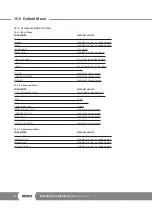
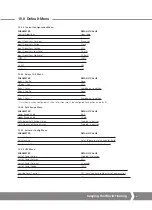
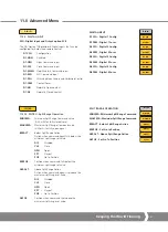
Page 40: ...tus access ADVANCED MENU No Default menu access DEFAULTS No Default default access 10 2 2 Advanced Menu PARAMETER DEFAULT VALUE CPT 4 Current Pos tx cal Set at factory to output 4 ma CPT 20 Current Pos tx cal Set at factory to output 20 ma SPEED 100 Stall Time out 2 0 Seconds Command Source Analog INFORMATION ACCESS No Default menu access CONTROL CFG ACC No Default menu access RELAY ACC No Default...

Page 41: ...ured for position on default 10 2 6 Split Range Menu PARAMETER DEFAULT VALUE Lower Range Value 4 mA Upper Range Value 20 mA CMD Below Split Range Action Disabled no action CMD Above Split Range Action Disabled no action 10 2 7 Actuator Config Menu PARAMETER DEFAULT VALUE Actuator Type Set at Factory to match actuator build Actuator Size Set at Factory to match actuator build Encoder Initialization...

Page 42: ...band FLTHST Fault History Access ADVANC Advanced Menu DEFLTS Default Menu Access STATUS CTRCFG CTRLAL IN DMP LOS TO LOS ACT LOS LO LOS HI ACTCFG RELAYS R1 CFG R1 FRM R2 CFG R2 POS ACTTYP ACTSIZ ENCINI SPLTRG MINCMD MAXCMD BSRACT ASRACT ASPOS BSRPOS UPS LOP AC LOP PO LOP TO OR REM OR LOC OR LST LOP SP DEFLTS LD CUST ST CUST LD FACT R2 FRM R1 POS R5 CFG R5 FRM R6 CFG R6 POS R6 FRM R5 POS R7 CFG R7 F...

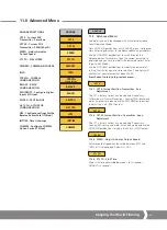
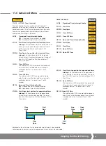
Page 43: ... SPAN 20 mA SPEED Adjust Actuator Output Speed STL TO STALL TIME CMDSRC COMMAND SOURCE INFO CTRCFG CONTROL CONFIGURATION RELAYS RELAY CONFIGURATION DIG INPUTS Configure Digital Inputs if fitted SPLTRG SPLIT RANGE ACT CFG ACTUATOR CONFIGURATION UPS Configure settings for the Reserve Power Pack if fitted INTTIM Timer Interrupt COMMS Configure COMMS Option Cards if fitted INTTIM CL TIE ST CLS SP OPN ...

Page 44: ...T Open Action BASIC CL LIM Close Limit zero OP LIM Open Limit span CMD4 Field Command Signal4 CMD20 Field Command Signal20 DBAND Deadband FLTHST Fault History Access ADVANC Advanced Menu DEFLTS Default Menu Access STATUS ACTCFG ACTTYP ACTSIZ ENCINI SPLTRG MINCMD MAXCMD BSRACT ASRACT ASPOS BSRPOS UPS LOP AC LOP PO LOP TO OR REM OR LOC OR LST LOP SP DEFLTS LD CUST ST CUST LD FACT COMMS MODBUS PROFIB...

Page 45: ... Menu Access STATUS CTRCFG CTRLAL IN DMP LOS TO LOS ACT LOS LO LOS HI ACTCFG RELAYS R1 CFG R1 FRM R2 CFG R2 POS ACTTYP ACTSIZ ENCINI SPLTRG MINCMD MAXCMD BSRACT ASRACT ASPOS BSRPOS UPS LOP AC LOP PO LOP TO OR REM OR LOC OR LST LOP SP DEFLTS LD CUST ST CUST LD FACT R2 FRM R1 POS R5 CFG R5 FRM R6 CFG R6 POS R6 FRM R5 POS R7 CFG R7 FRM R8 CFG R8 POS R8 FRM R7 POS COMMS MODBUS PROFIBUS PAKSCAN HART FF...

Page 46: ...FG Relay 5 Config R5 POS Relay 5 Pos R5 FRM Relay 5 Form R6 CFG Relay 6 Config R6 POS Relay 6 Pos R6 FRM Relay 6 Form R7 CFG Relay 7 Config R7 POS Relay 7 Pos R7 FRM Relay 7 Form R8 CFG Relay 8 Config R8 POS Relay 8 Pos R8 FRM Relay 8 Form INTTIM LOCREM Local Remote Operation MANJOG Manual Jog TORQ THRSTC Close Torque Thrust TORQ THRSTO Open Torque Thrust CL ACT Close Action OP ACT Open Action CL ...

Page 47: ...mum Split Range Command value 4 20 mA for fully closed zero MAXCMD Maximum Split Range Command value 4 20mA for fully open span BSRACT Below Split Range Action Action when command signal falls below the minimum split range set value DIS Disabled CLS Close OPN Open SPT Stayput POS Go to Position BSRPOS Position when command falls below the minimum split range set value ASRACT Above Split Range Acti...

Page 48: ...Fault History Access ADVANC Advanced Menu DEFLTS Default Menu Access STATUS SPLTRG MINCMD MAXCMD BSRACT ASRACT ASPOS BSRPOS UPS LOP AC LOP PO LOP TO OR REM OR LOC OR LST LOP SP DEFLTS LD CUST ST CUST LD FACT COMMS MODBUS PROFIBUS PAKSCAN HART FFBUS COM TO LOS ACT LOS PO MIN SP MAX SP PRM OC Primary Option RI CTL Remote Control Inputs 2W PRI 2 Wire Priority LOS AC RIRO Only LOS PO RIRO Only ESDACT ...

Page 49: ...9 seconds OP TIE Open end Timer Interrupt Enable OFF Opened end Timer Interrupt disabled ON Opened end Timer Interrupt enabled ST OPN Start Open start position for opened end timer interrupt Position above which the opened end timer interrupt is active when opening Can be set from 0 to 100 position Must be set above SP OPN Stop Open SP CLS Stop Close stop position for opened end timer interrupt Po...

Page 50: ...rofibus Address PRORT Profibus Redundancy Type PRORM Profibus Redundancy Mode PROT1 Profibus Termination1 PROT2 Profibus Termination2 GSDAC Profibus GSD Active Characterisation Active PAKSCAN PAKAD Pakscan Address PAKBD Pakscan Baud Rate HART HRTAD Hart Address HRTDS Hart Demand Source FOUNDATION FIELDBUS FFB FT Foundation Fieldbus Type DEVICENET DEVAD DeviceNet Address DEVBD DeviceNet Baud Rate F...

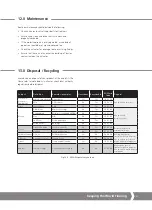
Page 51: ...oards All products Yes Yes 16 02 14 Use specialist recyclers Wire All Products No Yes 16 02 16 Glass Lens Window CMA No Yes 20 01 02 Metals Aluminium Brackets housings No Yes 20 01 40 Use specialist metal recyclers Copper Brass Wire motor windings PCBAs No Yes 20 01 40 Zinc N A No Yes 20 01 40 Iron Steel Gears and shafts No Yes 20 01 40 Mixed Metals Bushings No Yes 20 01 40 Plastics Glass filled n...

Page 52: ...e subject to change For the very latest version release visit our website at www rotork com The name Rotork is a registered trademark Rotork recognises all registered trademarks Published and produced in the UK by Rotork POWTC0319 Rotork is a corporate member of the Institute of Asset Management PUB094 019 00 Issue 04 19 www rotork com A full listing of our worldwide sales and service network is a...

Reviews: