6
Installation & Maintenance
Instructions
2.0 General Information
2.4 Receiving / Inspection
Carefully inspect for shipping damage. Damage to the
shipping carton is usually a good indication that it has
received rough handling. Report all damage immediately to
the freight carrier and Rotork.
Unpack the product and information packet taking care to
save the shipping carton and any packing material should
return be necessary. Verify that the items on the packing list
or bill of lading agree with your own documentation.
Rotork cannot accept responsibility for deterioration caused
on-site once the covers are removed. Every Rotork actuator
has been fully tested before leaving the factory to give
years of trouble free operation providing it is correctly
commissioned, installed and sealed.
WARNING
Before installing the actuator, make sure that it is
suitable for the intended application. If you are
unsure of the suitability of this equipment for your
installation consult Rotork prior to installation.
WARNING:
ELECTRIC SHOCK HAZARD
Installation and servicing must be performed only by
qualified personnel.
WARNING:
ELECTROSTATIC DISCHARGE
This equipment houses static sensitive devices. To
protect the internal components never touch the
printed circuit boards without using electrostatic
control procedures.
WARNING
Protection provided by the equipment may be
impaired if used in a manner not specified by Rotork.
2.5 Storage
If your actuator cannot be installed immediately store it in a
dry place until you are ready to connect incoming cables.
If the actuator has to be installed but cannot be cabled it is
recommended that any plastic cable entry plugs are replaced
with PTFE (Polytetrafluoroethylene) sealed metal plugs.
2.6 Equipment Return
If your Rotork actuator has been correctly installed and sealed
it will give years of trouble free service.
Should you require technical assistance or spares, Rotork
guarantees the best service in the world. Contact your local
Rotork representative or the factory direct at the adress on
the nameplate, quoting the actuator type and serial number.
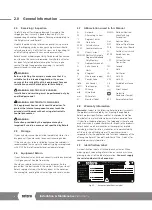
2.7 Abbreviations used in this Manual
A
Ampere
AC
Alternating Current
°C
Degrees Celsius
CW Clockwise
ACW Anti-clockwise
CCW Counter-clockwise
DC
Direct Current
EEPROM Electrically Erasable
Programmable Read
Only Memory
°F
Degrees Fahrenheit
G
Earth Ground
Hz Hertz
kg Kilogram
L
Line (power supply)
lbf
Pounds Force
lbf.in
Inch Pounds
lbf.ft
Foot Pounds
mA Milliamp
mfd Microfarad
mm Millimeters
N
Newton (force)
NEMA National Electrical
Manufacturing
Association
Nm
Newton Meter
NPT
National Pipe Thread
PCB
Printed Circuit Board
PL
Position Limit switch
RPM
Revolutions per
Minute
CPT
Current Position
Transmitter
SEC Second
V Volts
VA
Volt Amps
VAC
Volts AC
VDC
Volts DC
VR
Variable Resistance
W Watt
Direct current
Protective
Conductor Teminal
RPP
Reserve Power Pack
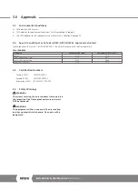
2.8 Warranty Information
Warranty:
Subject to the following, Rotork expressly warrants
the products manufactured by it as meeting the applicable
Rotork product specifications and that such products are free
from defects in material and workmanship for a period of one
(1) year from the date of delivery. The foregoing is the sole and
exclusive warranty made by Rotork with respect to the products.
Rotork makes no other warranties, either express or implied
(including, without limitation, warranties as to merchantability
or fitness for a particular purpose). The purchaser retains
responsibility for the application and functional adequacy of the
offering. See Rotork’s General Conditions of Sale - Product, for
complete warranty information.
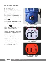
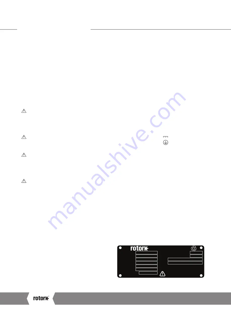
2.9 Identification Label
An identification label is attached to each actuator. When
ordering parts, requesting information or service assistance,
please provide all of the label information.
You must supply
the serial number with all enquiries.
Serial number
Wiring diagram
Actuator type
Output max.
Enclosure
Actuator supply
Rated current
www.
.com
ROTORK PROCESS CONTROLS
MILWAUKEE, WI, USA.
Unit weight
Year of manufacture
Kg
Amp
IP67
M00-00
M1895423942
CML-250
2224 N
120/240
1
2012
8
Fig 2.1
Actuator identification label
A4
US
US
A4
US
A4
US
A4

