7
3.6 ESD Signal
A dedicated ESD digital input is
provided with all standard actuators.
The actuator may be configured to Fail-
in- Position, Fail Close or Fail Open. The
ESD signal can also be configured to
override the Local Stop command.
Double -acting units without an
optional accumulator require power
to the motor in order to stroke the
actuator to the ESD position.
Refer to the wiring diagram for input
terminals. Refer to Section 9.5 for
settings.
3.7 Partial Stroke
A dedicated Partial Stroke input is
provided as a standard feature for
Open/Close applications. Its purpose is
to verify valve and actuator operation
without significant effect on valve flow.
Refer to the wiring diagram for input
terminals. Refer to Section 9.5 for
settings.
3.8 Limit Switches
When fitted, open and close limit
switches are pre-set at the factory to
correspond to the actuator mechanical
travel stops. Pre-set positions should
be checked to ensure full opening and
closing of the valve.
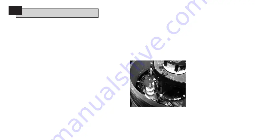
Should adjustment be required, they
must be manually set and are accessed
by removal of the control module cover.
The upper-most switch is the open
switch; the lower is the close switch.
Switch cam adjustment is by fingertip
rotation in either direction. Cams are
compression spring loaded and are held
in position by tapered centers.
Open and Close position limits must
also be set via controller configuration.
Refer to Section 8.
3.8.1 Open Switch Adjustment
Move the valve/actuator to the fully
open position. Locate the proper switch
cam. Push the cam down and rotate
anti-clockwise until the switch operates
and release the cam. The switch is now
set.
3.8.2 Closed Swtch Adjustment
Move the valve/actuator to the fully
closed position. Locate the proper
switch cam. Lift and turn the cam
clockwise until the switch operates and
release the cam. The switch is now set.
3.8.3 Four SPDT Option
Refer to DOC 1613.
3.9 Speed Control
Speed control is a standard feature only
on the spring stroke of spring return
actuators. For the hydraulic stroke of
spring-return actuators and for double-
acting actuators, it is an available option
requiring the addition of a hydraulic
power storage accumulator.
The speed of the hydraulic stroke is not
adjustable by the Extend speed control.
This is due to the nature of fixed
displacement pumps. The Extend speed
control should be fully anti-clockwise.
3.9.1 Spring-Return Adjustment
(No Accumulator)
Only the stroke time for the spring
stroke is adjustable. This is done with
the needle valve labeled Retract on the
hydraulic manifold. Loosen the jam nut
and turn the needle valve clockwise
to decrease the stroke time or anti-
clockwise to increase stroke time.
The speed of the hydraulic stroke is not
adjustable by the Extend speed control.
This is due to the nature of fixed
displacement pumps. The Extend speed
control should be fully anti-clockwise.
Operating your EH Actuator
continued
3


