-9-
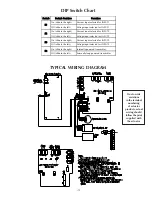
DIP Switch Chart
Switch
Switch Position
Function
On (slide to the right)
Current input selected for INPUT 1
Off (slide to the left)
Voltage input selected for INPUT 1
On (slide to the right)
Current input selected for INPUT 2
Off (slide to the left)
Voltage input selected for INPUT 2
On (slide to the right)
Current input selected for INPUT 3
Off (slide to the left)
Voltage input selected for INPUT 3
On (slide to the right)
Internally powered transmitter
Off (slide to the left)
Externally loop powered transmitter
S1
S2
S3
S4
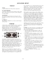
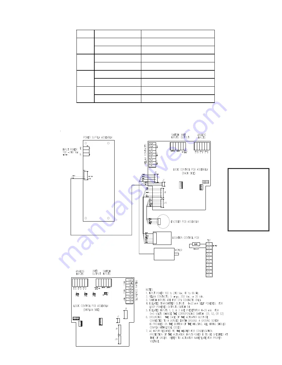
TYPICAL WIRING DIAGRAM
Due to wide
variations
in the terminal
numbering
of actuator
products, actual
wiring should
follow the print
supplied with
the actuator
.

