background image

-17-

SOFTWARE SETUP

6.3 Output Relays

The actuator has three output relays that are configurable by

the user.  They may be set to trigger on any one of thirteen

fault/alarm or actuator conditions.  They may also be

configured as ENERG ON FLT or DEENERG ON FLT.

6.3.1 R1 ASSIGN

The Relay may be triggered upon any one of the following

conditions:

Fault

Process Variable Low

Local

Process Variable High

Remote

Set Point Deviation Low

Manual

Set Point Deviation High

Auto

Command Low

Stall

Valve Position High

Valve Position Low

When assigned to NONE, the relay will not trigger but is set

to the state that was set up by the R1 CONFIG parameter.

6.3.2 R1 CONFIG

The output relay may be configured as ENERG ON FLT

(energized on fault), relay closes on the fault condition or

DEENERG ON FLT (de-energized on fault) relay opens on

fault condition.

6.3.3 R2 ASSIGN

See Relay 1 Assignment, this operates in the same fashion

but on the second output relay.

6.3.4 R2 CONFIG

See Relay 1 Configuration, this operates in the same fashion

but on the second output relay.

6.3.5 R3 ASSIGN

See Relay 1 Assignment, this operates in the same fashion

but on the third output relay.

6.3.6 R4 CONFIG

See Relay 1 Configuration, this operates in the same fashion

but on the third output relay.

6.4 Contact Inputs

The actuator is equipped with two contact inputs that may

be configured by the operator.

6.4.1 INPUT SW ACTIVE

Setting this parameter to YES enables input Switch 1.  When

active, the INPUT CONFIG and INPUT SW SET parameters

are also made accessible to the operator. If INPUT SW

ACTIVE is set to NO, no other Input switch 1 parameters are

accessible (not displayed) and switch 1 input is not used.

6.4.2 INPUT SW CONFIG

When Input switch 1 is enabled this parameter configures

whether the switch is normally open (NORM OPEN), action

is taken when the contact closes or normally closed (NORM

CLOSED), action is taken when the contact opens.

6.4.3 INPUT SW SET

The user has two options for actuator positioning when this

switch is activated.  It may be set to either LOCK (lock in

place) or DRVIE TO ZERO (run to the ZERO position) .

6.4.4 ORIDE SW SET

Setting this parameter to YES enables the input standby

switch.  When active, the Override Switch Configuration is

also made accessible to the operator. If the ORIDE SW SET is

set to NO, the Override Switch configuration parameter is

not accessible and the Override switch input is not used.

6.4.5 ORIDE SW CONFIG

When ORIDE SW SET is set to YES this configures whether

the switch is normally open (NORM OPEN), action is taken

when the contact closes or normally closed (NORM

CLOSED), action is taken when the contact opens.

When the override switch is activated the actuator will drive

to the ZERO position and the lower line of the display will

show OVERRIDE at all times.

Summary of Contents for GPSA Series

Page 1: ...Instruction Manual Established Leaders in Valve Actuation Publication P270E Issue 08 08 GPSA Series Electric Actuators and Control Systems...

Page 2: ...1...

Page 3: ...echanical Setup 8 DIP Switch Configuration 9 Typical Wiring Diagram 9 Actuator Setup 10 11 Menu Overview 12 Software Setup 13 19 Control Schemes 20 Troubleshooting Guide 21 Due to wide variations in t...

Page 4: ...it is suitable for the intended application If you are unsure of the suitability of this equipment for your installation consult Rotork Process Controls prior to proceeding WARNING SHOCK HAZARD Insta...

Page 5: ...uilt Sequential Number Month Built ABBREVIATIONS USED IN THIS MANUAL A or Amps Ampere ac Alternating Current C Degrees Celsius CW Clockwise CCW Counterclockwise dc Direct Current F Degrees Fahrenheit...

Page 6: ...F to 150 F 20 C to 65 C Enclosure Explosion proof for Class I Division 1 Groups C and D Dust ignition proof for Class II Division 1 Groups E F and G Type 4 indoor or outdoor Duty Cycle Continuous unr...

Page 7: ...dwheel Electronics Actuator Cover Actuator Base Magnetic Feedback Encoder Motor Screw Nut Screw Shaft Output Shaft Non Intrusive Momentary Switches for Setup and Diagnostics Vacuum Fluorescent Display...

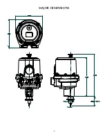
Page 8: ...7 MAJOR DIMENSIONS...

Page 9: ...monitoring indication The relays may be configured to energize or de energize on the assigned condition The contacts are rated at 10mA to 5A 250V AC 30V DC The relays will de energize under loss of po...

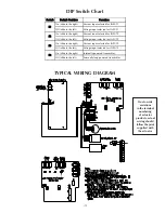
Page 10: ...he left Voltage input selected for INPUT 2 On slide to the right Current input selected for INPUT 3 Off slide to the left Voltage input selected for INPUT 3 On slide to the right Internally powered tr...

Page 11: ...e settings If the parameter is numeric the knob selections will increment or decrement the parameter respectively When updating a numeric parameter value holding a knob selection or will increase the...

Page 12: ...libration points up to 11 will be automatically available until the CAL PT X VAL parameter is set equal to the MAX POSITION parameter value set in step 1 When this occurs calibration is considered com...

Page 13: ...2 4 8 PV MAX 6 2 4 9 PV MIN 6 2 4 10 PV DAMP 6 2 4 11 PV HI ALRM 6 2 4 12 PV LO ALRM 6 2 4 13 PV ALRM DB 6 2 4 14 PROPOR GAIN 6 2 4 15 INTEGRAL TIME 6 2 4 16 CMD CHNG TIME 6 2 4 17 CMD POS VARI 6 2 4...

Page 14: ...btained locally when set to LOCAL or if it is obtained from the input signal on input pair number 3 when set to REMOTE SOFTWARE SETUP Configuration 6 1 Basic Parameters 6 1 1 DEADBAND This adjustment...

Page 15: ...signal must fall below the Process Variable High Alarm level by this amount to clear a Process Variable High Alarm The parameter may be set from 0 3 to 25 of the Process Variable signal range 6 2 3 8...

Page 16: ...le and it s associated parameters It is entirely configurable by the operator When selected for update the first of the four characters is highlighted The selections are used to scroll through the ava...

Page 17: ...is changed by 25 and the CMD CHNG TIME parameter is set to 30 seconds incre mental changes will be made to the system each control cycle to incorporate the correction over time so that it is fully im...

Page 18: ...or is equipped with two contact inputs that may be configured by the operator 6 4 1 INPUT SW ACTIVE Setting this parameter to YES enables input Switch 1 When active the INPUT CONFIG and INPUT SW SET p...

Page 19: ...er 6 5 4 3 CAL PT 2 VAL This is the unit value associated with the second calibration point of the valve 6 5 4 4 CAL POINT 3 11 These are the actual positions of the output shaft at additional calibra...

Page 20: ...or incompletely the changes will allow the actuator to run out of its expected range which could cause damage to the actuator and or to the devices to which it is connected This procedure should only...

Page 21: ...iable Feedback Input 2 Controller Actuator Drive Valve Closed Loop GPSA Controller Process Control Mode Actuator Output Local or Remote PV Setpoint Input 3 PV Sensor Process Variable Process Variable...

Page 22: ...r hunts in operation a Command signal is oscillating b Noise is present on command signal c Process variable is driving changing actuator position a Verify command signal is not oscillating Determine...

Page 23: ...22...

Page 24: ...rocess of on going product development Rotork reserves the right to amend and change specifications without prior notice Published data may be subject to change For the very latest version release vis...

Reviews: