-8-
General
The electrical installation, maintenance and use of these
actuators should be carried out in accordance with the
National Legislation and Statutory Provisions relating to the
safe use of this equipment, applicable to the site of installa-
tion.
For the UK: Electricity at Work Regulations 1989 and the
guidance given in the applicable edition of “IEEE Wiring
Regulations” should be applied. Also the user should be fully
aware of his duties under the Health and Safety act 1974.
For USA: NFPA70, National Electrical Code ® is applicable.
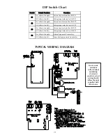
The basic wiring diagram is shown on page 9, however the
actual wiring must follow the print supplied with the actuator.
Input Power
Input power, (100-240VAC ±20%), terminates at TB1 on the
power supply board. Live and Neutral must be connected to
terminals 1 and 3 respectively. The power supply is auto-
sensing therefore no switch settings are required for selection
of input voltage range.
The incoming power supply earth ground must be securely
connected to the ground screw terminal located inside the
actuator base.
Command Wiring
The analog input signals are used for automatic positioning of
the actuator. The assignment of each channel is as follows:
Proportional: J3-1 (+ve) and J3-2 (-ve)
Process Variable: J3-3 (+ve) and J3-4 (-ve)
Remote Setpoint or Remote Ratio: J3-5 (+ve) and J3-6 (-ve)
Consult ‘Control Setup’ section of this document for more
information. The input signal may be configured for voltage
(1-5V) or current (4-20mA) and is achieved by use of dip
switches S1 – S3, see section titled ‘
Setting the Dip
Switches
’. Each analog input channel is fully isolated.
MECHANICAL SETUP
Relays
The GPSA provides 3 user configurable relays for position or
monitoring indication. The relays may be configured to
energize or de-energize on the assigned condition. The
contacts are rated at 10mA to 5A, 250V AC, 30V DC. The
relays will de-energize under loss of power.
The connections are as follows:
Relay 1: J1-7 Normally Closed
J1-8 Normally Open
J1-9 Common
Relay 2: J1-4 Normally Closed
J1-5 Normally Open
J1-6 Common
Relay 3: J1-1 Normally Closed
J1-2 Normally Open
J1-3 Common
Contact Inputs
The Contact Inputs provide an additional pair of isolated
inputs for specific control purposes, (see ‘
Start-up Informa-
tion
’ section of this document). These inputs are activated
by connecting the corresponding pair of terminals together.
Input SW should be wired to terminals J2-3 and J2-4. The
Stand-by switch is wired to J2-5 and J2-6. Information
regarding the configuration of these switches can be found in
the ‘
Start-up Information
’ section of this document.
Transmitter
A current loop transmitter provides a 4-20mA signal that
corresponds to the measured position. This may be either
loop powered or internally powered, (see the section titled
‘
Setting the Dip Switches
’). In the internally powered mode,
the feedback signal wires connect to terminals 2 (+ve) and 1
(-ve) of J2 respectively. In the loop powered mode however,
the signal wires connect to terminals 1 (+ve) and 2 (-ve) of
J2 respectively. The transmitter is fully isolated.
Setting the Dip Switches
There are four dip switches situated on the main logic PCB
that are used for actuator configuration. They are located
behind the display near the display board standoffs. Switches
S1 – S3 determine the type of command signal, (voltage or
current) used by the actuator, for analog inputs 1 – 3 respec-
tively. Switch S4 is used to select between a loop powered
and internally powered current transmitter. It should be
noted that the orientation of the transmitter’s terminals is
different for the two modes.

