A4
US
US
A4
US
A4
US
A4
A4
US
US
A4
US
A4
A4
US
24
IQ3 Full Configuration Manual – Section: Settings
2.3.2-6 Control – Remote – Analogue Option
Remote Control
Hardwired
Control Source
Partial Stroke
Positioning
Auxiliary Mask
Analogue
Analogue
Signal Type
mA
Volts
Signal Range
20mA
Invert
On
Off
Manual-Auto
On
Off
Set Low Signal
Set High Signal
1/6
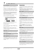
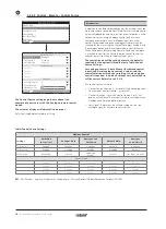
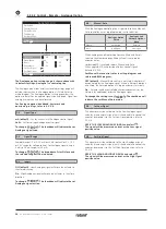
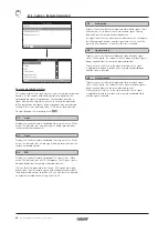
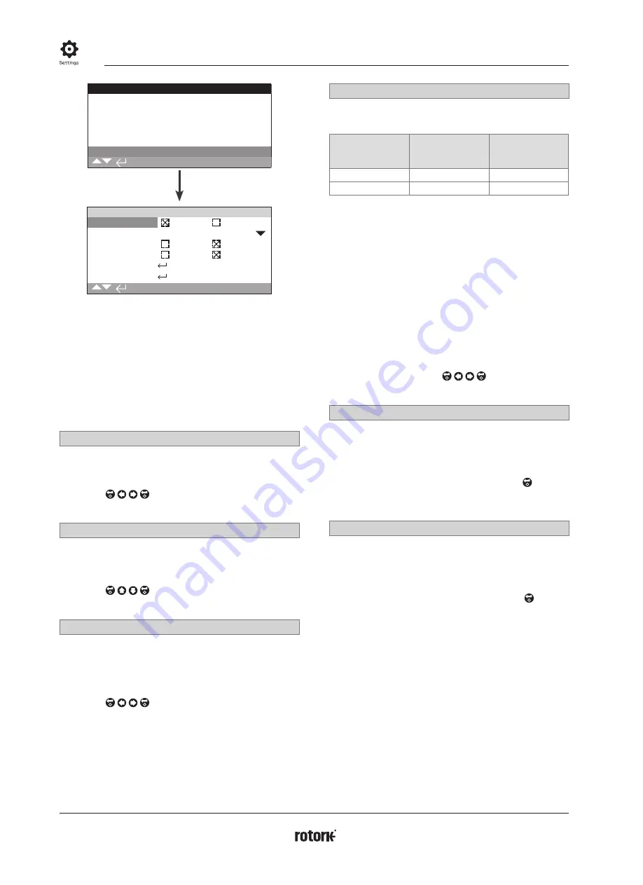
The Analogue option settings page is shown above with
its default settings. Analogue is a control option.
The Analogue menu item and its associated settings page will
only be shown when the Analogue option is fitted. Refer to
wiring diagram. The Analogue option setting page allows the
option to be set for the applied signal type and range. Signal low
and high values can also be calibrated.
For Analogue option; deadband, hysteresis and
positioning settings, refer to 2.3.2-4.
1/6
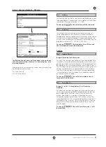
Signal Type
mA (default)
– Set for current (mA) Analogue control signal.
Volts
– Set for voltage Analogue control signal.
To change, . The checkbox will indicate the set
Analogue signal type.
2/6
Signal Range
Available ranges: 5 mA, 10 mA or 20 mA (default) or 5 V, 10 V
or 20 V range for voltage control. For Analogue signal using a
4 mA to 20 mA range, set 20 mA.
To change, . The drop down list will close and
the selected range will be indicated.
3/6
Invert
Off (default)
– Low Analogue signal will move the actuator in
the close direction.
On
- High Analogue signal will move the actuator in the close
direction.
To change, . The checkbox will indicate the set
Analogue signal action.
4/6
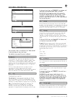
Manual-Auto
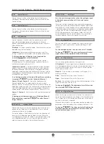
With the Analogue control option it is possible to have Manual/
Auto control by a user supplied remote switch selection:
Analogue Option
Fitted
Analogue and
Network Options
fitted
Manual
Hardwired
Network
Auto
Analogue
Analogue
When Analogue and Network options are fitted and Auto is
selected, the Network option fitted will continue to report
actuator status.
Hardwired ESD is available in both Manual and Auto.
When applied, ESD will override all other control signals.
Refer to 2.4 ESD.
For Manual Auto control, refer to wiring diagram and
referenced RWS diagram.
OFF (default)
– Manual/Auto control is not used. Actuator will
be controlled by the Analogue signal. Where a Network option is
also fitted, the Network option will report actuator status only.
On
– Actuator can be controlled by hardwired contacts or the
Network (as applicable) or by the Analogue signal.
To change the settings use, . The checkbox will
indicate the set Manual/Auto mode.
5/6
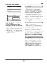
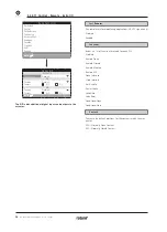
Set Low Signal
The actuator must be calibrated to the Low Analogue signal
value. By measuring this signal it will then be able to control the
actuator by moving it to the Set Low Signal position, refer to
2.3.2-4.
APPLY THE LOW ANALOGUE SIGNAL and select .
The signal will be measured and set as the Low signal
position value.
6/6
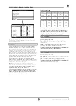
Set High Signal
The actuator must be calibrated to the High Analogue signal
value. By measuring this signal it will then be able to control the
actuator by moving it to the Set High Signal position, refer to
2.3.2-4.
APPLY THE HIGH ANALOGUE SIGNAL and select .
The signal will be measured and set as the High signal
position value.
Summary of Contents for IQ Multi-Turn
Page 2: ...2...

