background image

A4

US

US

A4

US

A4

US

A4

A4

US

 US

 A4

 US

 A4

A4

US

44 


IQ3 Full Configuration Manual – Section: Data Log

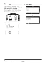
Data logs, which are able to store vast amounts of operational 
and environmental information, are provided as standard on the 
IQ. Due to the nature of the graphical display, information can 
be displayed locally at the actuator using the supplied Rotork 

Bluetooth

®

 Setting Tool Pro.

The stored information can be used to view, diagnose and trend 
any type of operational condition that may affect the valve, 
actuator or process. With asset management becoming preferred, 
the data log helps to achieve goals set out by process conditions.

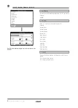
Refer to section 1.2 for connecting to the actuator. Once 
connected, use the four directional arrows to navigate to the 
main icon menu. From here you can highlight and select the Data 
log icon:

Open Limit

Main Menu

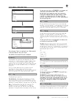
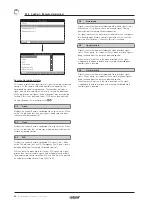
The first time you enter the data log menu, you will be given the 
opportunity to set the current time and date. This time and date 
is ONLY for the local display and does not affect the dates when 
you download the data log for viewing in Insight2. If you want 
to set the current time and date, please refer to section 4.6 for 
details.

Set Date

Open Limit

Hour

9

23

14

5

44

2013

Day

Minute

Month

Second

Year

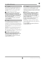
Check the current time and press enter  . You will now be 
shown the main Data log menu below:

Stopped

Data log Menu

Torque Logs

Event Logs
Trend Logs
Operation Logs
Partial Stroke
Set Log Date

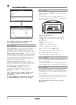
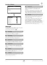
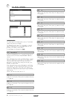
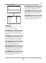
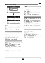
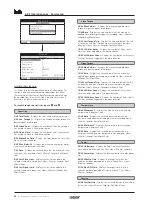
4.  Data Log

4  Data Log menu structure   


Page

 4.1 

 Torque 

Logs         45


4.1.1 

Valve Torque Live   


45


4.1.2 

Valve Torque Profile  


46


4.1.3   Valve Torque Reference   


46

 4.2 

 Event 

Logs 

         47


4.2.1   Control Event Log   


47


4.2.1-1  Event Log Filter   


48


4.2.1-2  Control Event Log   


50


4.2.2   Error Event Log   


51

 4.3 

 Trend 

Logs 

         51


4.3.1 

 Temperature          52

  4.3.2 


Battery 

         52


4.3.3   Vibration Average   


53

  4.3.4 


Vibration 

Peak 

       53

 4.4 

 Operation 

Logs 

        54


4.4.1   Starts Profile  


54

  4.4.2 


Statistics         55

  4.4.3 


Service 

Log 

        56

  4.4.4 


Bluetooth 

Log 

       57

 4.5 

 Partial 

Stroke 

        58


4.5.1   Partial Stroke Results 


58


4.5.2   Partial Stroke Torque 


59


4.6  

Set Log Date   


59

Summary of Contents for IQ Multi-Turn

Page 1: ...Keeping the World Flowing IQ and IQT full configuration status and monitoring user manual IQ Multi Turn and IQT Part Turn Electric Valve Actuators IQ Range...

Page 2: ...2...
Page 3: ...________________51 4 4 Data Log Operation Logs_____________ 54 4 5 Data Log Partial Stroke Logs__________ 58 4 6 Data Log Set Log Date_______________ 59 5 Assets_______________________________ 60 5 1...

Page 4: ...at the bottom left Pages Functions and Index The display indicates the number of each function as it is highlighted along with the total number of functions on that page In the example below Action i...

Page 5: ...ved and shown as checked on the page To exit the checkbox without saving a new setting press to return to the page Slider controls Slider controls graphically indicate the set value followed by the ex...

Page 6: ...etting Tool will automatically connect using Bluetooth which takes up to 5 seconds Connection is indicated by a blue light on the tool and in the actuator display window Once connected the tool can be...

Page 7: ...played Press to return to the page Set the red selector to Local or Stop to proceed with setting With the actuator selected to Local or Stop and when any setting function is selected the Password scre...

Page 8: ...OP Bypass Pos 5 Closing On Off CL Bypass Pos 95 1 15 IQT builds only The Limits page is shown above with the default settings Close Settings 1 15 Close Direction Sets the output rotation direction re...

Page 9: ...en limit position refer to testing below The Closed Limit position must be set by moving the actuator to the valve Closed Limit position and pressing The actuator will display the following Instructio...

Page 10: ...should be consulted to confirm the valve structure and interface components can withstand the additional torque thrust 11 15 Opening Opening torque limit protection can be bypassed over a portion of...

Page 11: ...ay contact can be set to one of the functions shown in the table below and its contact type can be set as Normally Open NO or Normally Closed NC If Pos Open function is selected the position at which...

Page 12: ...ng which constitutes an alarm out of the function list triggers this alarm Bat Backup Avail Checks availability of battery checks if battery is charged Bat Backup Ctrl Checks if the battery is in cont...

Page 13: ...active the yellow lights flash alternately at approximately 0 5 second intervals Refer to 5 7 Alarm LED Off Alarm The yellow lights are off when mid travel If an alarm is active the yellow lights fla...

Page 14: ...osition On 4 mA output at Open Limit position 20 mA output at Closed Limit position To change the analogue output mode The checkbox will indicate the selected mode 2 2 3 Indication Analogue Settings L...

Page 15: ...approximately 10 m 30 ft depending on environment The black close open selector remains active No default Setting Tool close open and stop control keys disabled Local control is by close open stop sel...

Page 16: ...3 2 8 HART Option Analogue 2 3 2 9 Modbus Option Network 2 3 2 10 Extra I O Option Hardwired 2 3 2 11 Foundation Fieldbus Option Network N A When Foundation Fieldbus is fitted it will be included in...

Page 17: ...nals are applied to the closed or the open interlock input If only one interlock is required for example an interlock to prevent closed operation the open interlock must be linked out Conditional Clos...

Page 18: ...rt actuator status The control source will be set by Rotork to the defaults required for the option s fitted Refer to Table Control Source Settings For analogue control if both Manual hardwired contro...

Page 19: ...is fitted after manufacture the allocation will be set to the fitted option type by Rotork Service Where the user upgrades an actuator to include a new control option using a kit supplied by Rotork th...

Page 20: ...and then return to the Open Limit position Close The partial stroke test will start from the Closed limit position move open to the position set for 3 6 To Position and then return to the Close Limit...

Page 21: ...earer to the DV position The actuator will not restart unless it overshoots and runs outside the deadband or a new command places the new desired position outside the deadband Refer to figure 2 3 1 To...

Page 22: ...rmally this will be set at Open Limit position 100 unless positioning is required over a reduced portion of full valve travel for example to increase positioning resolution for a butterfly valve where...

Page 23: ...n and a Network option are fitted and hardwired ESD control is required Auxiliary 4 set to ESD ensure Auxiliary contact 4 setup is matched to the ESD configuration when signal setting Refer to 2 4 The...

Page 24: ...nal action 4 6 Manual Auto With the Analogue control option it is possible to have Manual Auto control by a user supplied remote switch selection Analogue Option Fitted Analogue and Network Options fi...

Page 25: ...change The drop down list will close and the selected baud rate will be indicated Position 3 8 Update Time s Range 0 Disabled to 255 seconds Set when mid travel positioning control is required Update...

Page 26: ...e Deviation will be indicated 7 8 Filter Set to enable or disable auto reporting of the historical torque logs Auto The Pakscan option will automatically report the 6 historical torque logs for each d...

Page 27: ...1 Termination 2 Profibus networks require active termination at each end of the highway Profibus option has active termination 2 sets for dual built in which can be switched in or out of the circuit O...

Page 28: ...uring this signal it will then be able to control the actuator by moving it to the Set High Signal position refer to 2 3 2 4 Positioning APPLY THE HIGH ANALOGUE SIGNAL and select the signal will be me...

Page 29: ...ermination resistors will be switched in for both channels To change The checkbox will indicate the set termination mode 3 6 Baud Rate The Modbus option must be set to the RS485 highway baud rate Chan...

Page 30: ...9 The DIO adds additional digital inputs and outputs to the actuator Fast Remotes Fast remotes are for modulating applications 24 VDC signals only Disabled Enabled Functions Below is a list of functi...

Page 31: ...area of the slider control for Closing and Opening will be the timed section If timed operation is no longer required Closing and Opening positions should both be set to 0 or 100 depending on the Sta...

Page 32: ...nput Normally Open N O contact making Removed ESD will be active when the signal is removed from the ESD input Normally Closed N C contact breaking Note If the analogue option and a Network option are...

Page 33: ...errides the Interrupter Timer Under ESD control the timer will be overridden and the actuator will run continuously to the set ESD position at normal speed WARNING In this mode when under ESD control...

Page 34: ...uired Bluetooth security level can be set and made non editable by Rotork Contact Rotork To change The drop down list will close and the selected Bluetooth security level will be indicated 2 5 Change...

Page 35: ...restore the default settings A warning will be given to continue All settings must then be checked set as required for valve operation and process control indication 2 3 Copy High level access only R...

Page 36: ...ction 1 2 for connecting to the actuator Once connected navigate to the main icon menu and using the four directional arrows highlight and select the Status Icon Open Limit 3 Status menu Page 3 1 Cont...

Page 37: ...s have been set to stop the actuator will not move to position regardless of the local or remote control signals it receives The ESD function has the ability to override Local Stop Refer to 2 4 4 6 Lo...

Page 38: ...m the remote hardwired control ESD can be set to open close or stayput ESD signals are higher priority than local or remote signals and will operate under both local and remote control selection ESD c...

Page 39: ...close or stayput ESD signals are higher priority than local or remote signals and will operate under both local and remote control selection ESD can also be set to operate an actuator selected to Loca...

Page 40: ...Check valve operation by hand 4 8 Motor Over Temp Displays the Motor Over Temperature alarm status When active this alarm indicates that the motor is over temperature and the thermostat has tripped Ch...

Page 41: ...e actuator is at the open limit 6 8 Closed Limit Displays the Closed Limit status When active this status indicates that the actuator is at the closed limit 7 8 PStroke Active Displays the Partial Str...

Page 42: ...ed An active relay status indicates the actuator has a fault present and the actuator is not available for remote control For each relay function please refer to 2 2 1 2 13 S1 Displays the S1 relay st...

Page 43: ...atus When active this status indicates that a fault with the absolute encoder has occurred Check the encoder operation and loom 4 8 Hardware Option Displays the communication fault status between the...

Page 44: ...and date This time and date is ONLY for the local display and does not affect the dates when you download the data log for viewing in Insight2 If you want to set the current time and date please refer...

Page 45: ...e Live This screen displays two torque graphs showing live torque percentage output against the actuator position for open and close directions Pressing the and arrows moves the cursor between the ope...

Page 46: ...0 0 100 Position Pos 36 T 100 Pos Position T Torque Valve Torque Reference The graph displays two torque profiles detailing the opening and closing torque as a percentage of rated torque by valve pos...

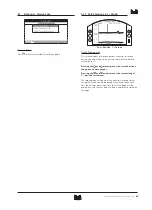
Page 47: ...on Data Log 47 4 2 Data Log Event Logs Stopped Event Logs Control Event Log Error Event Log Event Logs Press to view the selected Event Log 4 2 1 Event Logs Control Event Log Stopped Control Event Log...

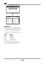
Page 48: ...p Shows hides stop events 6 59 Local Shows hides local events 7 59 Remote Shows hides remote events Remote Hardwired Control 8 59 Open Shows hides remote hardwired control open events 9 59 Close Shows...

Page 49: ...n status events 36 59 Moving Closed Shows hides moving closed status events 37 59 Contactor CW Shows hides clockwise contactor energised status events 38 59 Contactor ACW Shows hides anti clockwise co...

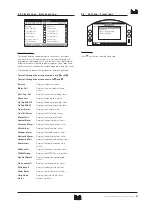
Page 50: ...ed log of actuator s control events The parameters that are displayed in this screen are determined by the selections made in the control event filter To view each event first select the parameters th...

Page 51: ...status Phase Loss Displays the phase loss status TrqTrip Mid OP Displays the open torque trip status TrqTrip Mid CL Displays the close torque trip status Trq Hi Alarm Displays the Hi alarm status Trq...

Page 52: ...an effect on operational conditions Pressing the or arrows moves the cursor along the graph by 1 hour 1 day 1 month 1 year increments Pressing the key cycles through the timescales of 24 hours 30 day...

Page 53: ...ibration and is not intended for accurate vibration analysis Pressing the and arrows cycles through the X Y and Z axis Pressing the or arrows moves the cursor along the graph by 1 hour 1 day 1 month 1...

Page 54: ...100 of starts at each end of travel but for modulating duty the graph will be spread as in the example above To prevent the scaling of the display exceeding the LCD capability all percentages of star...

Page 55: ...te and time that the actuators maximum closing torque was reached 9 24 Ave Torque Displays the actuators average torque as a percentage Power 10 24 Motor Run Time Displays the total motor running time...

Page 56: ...Last Torque Trip Displays the time and date of the last instance the actuator s torque trip was activated in the close direction Hours Minutes Seconds Day Month Year 13 28 Hi Alarm Count Displays the...

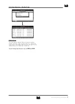
Page 57: ...10 15 49 15 09 05 2013 BST 100E86D24 10 07 56 33 10 05 2013 BST 100E86D24 10 08 06 27 10 05 2013 BST 100E86D24 10 08 26 26 10 05 2013 BST 100E86D24 10 Bluetooth Log This screen displays a log of all...

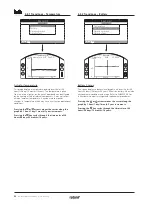
Page 58: ...Stopped Time Result 09 10 56 02 01 2013 10 05 02 14 02 2013 10 23 24 16 02 2013 12 24 43 19 03 2013 14 38 57 20 05 2013 15 02 23 26 05 2013 Partial Stroke Results This screen displays the results of...

Page 59: ...and its condition Pressing the and arrows moves the cursor between the open and close graphs Pressing the and arrows moves the cursor along at 1 position increments 4 6 Data Log Set Log Date Set Date...

Page 60: ...that data regarding the valve actuator tag valve details and process information are populated by the user or their agent Rotork will populate actuator build data automatically on manufacture Other a...

Page 61: ...uator Nameplate will be shown on the actuators set home screen display The tag name entered should be the valve and or actuator reference that identifies the asset within the site process control sche...

Page 62: ...depending on certification Non Hazardous IEC50529 Non Hazardous IEC50529 Canada IP68 IP68 CSA Hazardous ATEX EEA Hazardous IEC regional Hazardous US NEC500 II 2 GD EXD IIB T4 IEC EXD IIB T4 FM GRPS C...

Page 63: ...isplays the software version of the position sensor for SIL actuators Torque Sensor 17 22 Serial No Displays the serial number of the torque sensor IQT3 Motor Control Board 19 22 Software Version Disp...

Page 64: ...the valve manufacturer 7 10 Service Fluid Displays the valve service fluid 8 10 Service Temp Displays the valve service temperature 9 10 Location Displays the recorded location of the valve 10 10 Inst...

Page 65: ...assword has been entered Actuator service alarms are meant for indication only and will aid the user to schedule effective maintenance of the actuator valve Service torque alarms will only display a v...

Page 66: ...AMUR 107 diagnostics are NAMUR Allocation Description Alarm MAN Maintenance required N107 Maintenance OOS Out of specification N107 Out of Specification FNC Function check N107 Function Check FAI Fail...

Page 67: ...lure 13 24 Actuator Fail Allows the user to set NAMUR 107 diagnostics for actuator failure 14 24 Comms Loss Allows the user to set NAMUR 107 diagnostics for communications loss 15 24 Opt Not Detect Al...

Page 68: ...lished data may be subject to change For the very latest version release visit our website at www rotork com The name Rotork is a registered trademark Rotork recognises all registered trademarks The B...

Reviews: