A4
US
US
A4
US
A4
US
A4
A4
US
US
A4
US
A4
A4
US
62
IQ3 Full Configuration Manual – Section: Assets
6/11
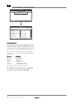
WiringDiag
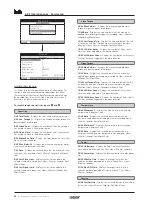
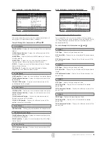
Displays the actuator Wiring Diagram number. Standard wiring
diagrams can be downloaded from http://wiring.rotork.com
using the wiring diagram selector link.
Wiring Diagrams prefixed "WD" are non-standard and user
specific. For a copy, contact Rotork.
7/11
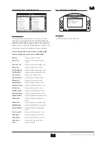
Speed
Displays the actuator output speed in RPM. If a 2nd stage
gearbox is used in combination with the actuator, the
combination output speed will be subject to the gearbox ratio.
For multi-turn combinations (gearbox types prefixed "IB", "IS" or
"MTW" refer to 5.3) divide the displayed speed by the gearbox
ratio to obtain the combination output speed in rpm.
For quarter-turn combinations (gearbox types prefixed "IW",
"IWD" or "MOW" refer to 5.3) divide the gearbox ratio by 4
then divide the result by the actuator speed (RPM) and multiply
by 60 to get the 90° operating time in seconds.
For actuator types "IQL" or "IQML", the speed quoted is the
linear output travel in mm/second.
For IQT builds, speed is quoted in seconds per 90º operation at
maximum rated speed.
8/11
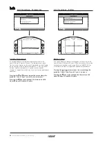
MaxTorque
Displays the actuator maximum (catalogue) rated torque in
Newton metres (Nm). The maximum rated torque is that at
100% torque setting. The torque may be set in the range 40%
to 100%, refer to 2.1. Unless specified with order, on despatch,
the torque will be set at 40%.
9/11
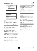
Enclosure
Displays the actuator enclosure type. For full details, refer also to
the actuator physical nameplate.
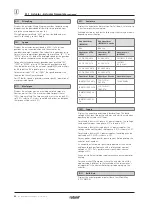
Available enclosures include the following. Others may be shown
depending on certification.
Non Hazardous
(IEC50529)
Non Hazardous
(IEC50529) Canada
IP68
IP68 CSA
Hazardous ATEX
(EEA)
Hazardous IEC
(regional)
Hazardous US
(NEC500)
II 2 GD EXD IIB T4
IEC EXD IIB T4
FM GRPS C,D,E,F&G
II 2 GD EXD IIC T4
IEC EXD IIC T4
FM GRPS
B,C,D,E,F&G
II 2 GD EXDE IIB T4
IEC EXDE IIB T4
II 2 GD EXDE IIC T4
IEC EXDE IIC T4
Hazardous Brazil
Hazardous Canada
Hazardous Japan
INMETRO EXD IIB T4
CSA CL1DIV1
GRCD T4
TIIS (EXDIIBT4X)
INMETRO EXD IIC T4
CSA CLI DIV1
GRBCDT4
INMETRO EXDE IIB
T4
INMETRO EXDE IIC
T4
10/11
Supply
Displays the actuator power supply build voltage. The build
voltage is that specified by the end user and must be used when
operating the actuator at all times.
For actuators built with 3 phase AC power supplies, the voltage
can be confirmed as three phase if IQ is shown in 3/11.
For actuators built with single phase AC power supplies, the
voltage can be confirmed as single phase if IQS is shown in 3/11.
For actuators built with DC power supplies, the voltage can be
confirmed as DC if IQD is shown in 3/11.
For any power supply queries please contact Rotork quoting the
actuator serial number.
As standard, actuators are specified to operate at their stated
catalogue torque performance with a tolerance of nominal
v/- 10%. Duty performance is specified at nominal
v/-0%.
Excess or insufficient voltage supply may cause increased motor
heating.
For valve maker FAT purposes, where the actuator is built for
a power supply different to that available at the valve maker"s
or integrator"s site, contact Rotork prior to powering up the
actuator.
11/11
Build Date
Displays the actuator production test date. YearMonthDay
(YYYYMMDD).
5.1.1 Actuator – Actuator Nameplate
continued
Summary of Contents for IQ Multi-Turn
Page 2: ...2...


