background image

IQT3 manual – Section: Mounting the Actuator

   13

6.  Mounting the Actuator

 Refer to Section 11 Weights and 

Measures for actuator weight.

6.1  IQT Actuators

The IQT range of actuators are suitable 

for part turn applications requiring up to 

60 starts per hour.

6.2  IQTM Actuators

The IQTM range of actuators are suitable 

for modulating control duty of up to 

1200 starts per hour in accordance with 

IEC 60034-1 to S4 50%. Commissioning 

of IQTM range actuators is identical to 

the standard IQT (refer to Sections 7, 8 

and 9).

6.3  IQTF Actuators

The IQTF range of actuators are suitable 

for part-turn and multi-turn, non-thrust 

applications requiring low speed and low 

operating turns. Commissioning of IQTF 

range actuators is similar to the standard 

IQT (refer to Sections 7, 8 and 9).

6.4  Lifting the Actuator

Ensure the valve is secure before fitting 

the actuator, as the combination may be 

top heavy and therefore unstable.

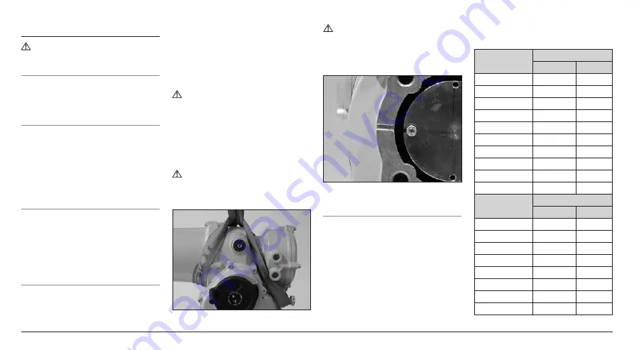
When lifting the actuator using 

mechanical lifting equipment certified 

slings should be attached as indicated 

in Figure 5. At all times trained and 

experienced personnel should ensure 

safe lifting, particularly when mounting 

actuators.

 WARNING: Do not lift the 

actuator by the handwheel.

A suitable mounting flange conforming 

to ISO 5210 or USA Standard MSS 

SP101 must be fitted to the valve. 

Actuator to valve fixing must conform 

to; Material Specification ISO Class 8.8, 

yield strength 628 N/sq mm.

 WARNING: Do not lift the 

actuator and valve combination via 

the actuator. Always lift the valve/

actuator assembly via the valve.


Fig. 6.4.1 

 WARNING: The actuator should 

be fully supported until full valve 

stem engagement is achieved and 

the actuator is secured to the valve 

flange.

Fig. 6.4.2 


6.5  Securing Actuator to Valve

Before engagement ensure that the 

actuator and valve are in the same 

position (i.e. closed) and the drive bush-

machining matches the stem position. 

Actuator position can be determined 

using the display (refer to section 3.3 

page 4) and if necessary can be moved 

using the handwheel (refer to section 

3.1 page 3). It may be necessary to 

adjust the stop bolts to enable sufficient 

travel. Refer to section 5.6. 

Tighten down onto valve flange to the 

required torque, see table B.

Imperial Size

Torque

Nm

lbf.ft

1

/

4

 - Hex

6.7

4.9

5

/

16

 - Hex

12.6

9.3

3

/

8

 - Hex

21.4

15.8

7

/

16

 - Hex

33.6

24.8

1

/

2

 - Hex

50.8

37.4

9

/

16

 - Hex

71.5

52.7

5

/

8

 - Hex

99.2

73.2

3

/

4

 - Hex

170.8

126.0

7

/

8

 - Hex

271.3

200.1

1 - Hex

406.0

299.5

Metric Size

Torque

Nm

lbf.ft

M5 - Hex

3.0

2.2

M6 - Hex

5.4

4.0

M8 - Hex

12.8

9.4

M10 - Hex

25.0

18.4

M12 - Hex

42.9

31.6

M16 - Hex

100.5

74.2

M20 - Hex

198.2

146.2

M24 - Hex

340.3

251.0

Table B

Summary of Contents for IQT3

Page 1: ...nance This manual must be consulted where ever this symbol is marked This manual contains important safety information Please ensure it is thoroughly read and understood before installing operating or...

Page 2: ...IQTM Actuators 13 6 3 IQTF Actuators 13 6 4 Lifting the Actuator 13 6 5 Securing Actuator to Valve 13 7 Cable Connections______________________ 14 7 1 Terminal Block Layout 14 7 2 Earth Ground Connec...

Page 3: ...l Cover Display Window Motor Cover Terminal Cover Conduit Entries Standard Conduit Entries Optional Local Remote Stop Selector Base Travel Stops Protective Earth Point Name Plate Battery Sealing Plug...

Page 4: ...ous area a The BTST function must be checked by ensuring that the red or green LED either in the clear window or under the Enter key of the BTST illuminates when any button is pressed If an LED does n...

Page 5: ...setting of torque levels position limits and all other control and indication functions can be made safely quickly and conveniently even in hazardous locations The IQ allows commissioning and adjustme...

Page 6: ...rs is forbidden in the hazardous area unless this is done under a special permit to work otherwise all power should be isolated and the actuator moved to a non hazardous area for repair or attention W...

Page 7: ...ronics Motor enclosures Explosionproof Class I Div 1 Groups B C D 40 to 70 o C Electronics Motor enclosures Explosionproof Class I Div 1 Groups B C D 50 to 40 o C Electronics Motor enclosures CSA Appr...

Page 8: ...d Auto lever can be locked in either position using a padlock with a 6 5 mm hasp Locking the lever in the hand position prevents electrical operation of the actuator moving the valve 4 2 Operating Ele...

Page 9: ...n will be displayed when a battery is detected as low or discharged Battery low or Discharged will also be displayed in the text display above 8 Infra Red Icon This icon flashes during setting tool co...

Page 10: ...able home screens until the required one is displayed The selected screen will remain displayed for approximately 5 minutes after the last setting tool command or until the actuator power is cycled Pe...

Page 11: ...icon will be supported with text in the bottom line indicating the particular alarm or if more than one is present each alarm will be displayed in sequence Fig 4 7 1 shows the status example TORQUE TR...

Page 12: ...bush Capscrews can be used to remove the drive bush by screwing into the drive bush as shown in figure 5 2 1 Fig 5 2 1 The range of IQT drive bushes is shown in figure 5 2 2 Please refer to PUB002 038...

Page 13: ...A suitable mounting flange conforming to ISO 5210 or USA Standard MSS SP101 must be fitted to the valve Actuator to valve fixing must conform to Material Specification ISO Class 8 8 yield strength 628...

Page 14: ...PUB002 018 3 phase actuators or PUB002 019 single phase actuators The switch or circuit breaker shall disconnect both poles of a three phase supply WARNING The maximum supply for actuators connected t...

Page 15: ...agram is replaced in the terminal compartment To ensure secure electrical connections it is important that the requisite washers are used as shown in Figure 7 5 1 Failure to do so may result in connec...

Page 16: ...TE WARRANTY This instruction details the basic settings that must be completed before the actuator is put into service ELECTRICAL OPERATION MUST NOT TAKE PLACE UNTIL THE BASIC SETTINGS HAVE BEEN MADE...

Page 17: ...ng an infra red command This means that the user must be in close proximity and in direct line of sight of the actuator Point the setting tool at the actuator display window within a range 0 25 m 10 i...

Page 18: ...ected to Local or Stop and when any function is selected the Password screen will be displayed Fig 8 2 2 The factory set default password ROTORK is displayed and the OK key is highlighted Press the ke...

Page 19: ...ti Action Limit Torque Torque 100 SetLimit OpenSettings Action Limit Torque Torque 60 2 15 LED INDICATION R RED G GREEN Y YELLOW B BLUE Y Y Fig 8 2 6 The password will be requested the first time a fu...

Page 20: ...g the keys and press to select The setting first selected to be changed will require a password to be entered refer to section 8 2 The limit settings are shown below with their factory default values...

Page 21: ...to close the valve can be set between 40 and 100 of rated The actuator rated torque value is shown on its nameplate Press to select Close Torque function Use key to decrease value and key to increase...

Page 22: ...imately 150 of rated to be available The valvemaker integrator should be consulted to confirm the valve structure and interface components can withstand the additional torque thrust 11 15 Opening Open...

Page 23: ...lose limit first and then the Open limit During this time the actuator will run without warning through its full travel No limits will be set until the full cycle has been completed If the actuator de...

Page 24: ...re is not an excessive build up of dust or contaminant on the actuator Check for any loss of lubricant refer to section 11 for lubricants The Actuator Battery The battery supports the actuator valve p...

Page 25: ...ar oil changes refer to Section 11 Weights and Measures Torque and Position Monitoring The IQT range of actuators incorporate real time instantaneous Torque Position monitoring as standard Torque Posi...

Page 26: ...tals Aluminium Gearcases and covers No Yes 17 04 02 Use licensed recyclers Copper Brass Wire IQ gears motor windings No Yes 17 04 01 Zinc IQ clutch Ring and associated components No Yes 17 04 04 Iron...

Page 27: ...F585B 600ml 1 3 pint US Size 2 IQT 1000 2000 3000 Castrol Aero HF585B 1600ml 3 4 pint US Base assembly O rings use either Multis EP2 Lithoshield EP2 or equivalent for all temperature ranges between 50...

Page 28: ...04 F Ex dbe IIC T4 T6 Gb Ex tb IIIC T120 C T80 C Db IP66 IP68 Temperature 20 C to 70 C 4 F to 158 F Option 30 C to 70 C 22 F to 158 F Option 40 C to 70 C 40 F to 158 F Option 50 C to 40 C 58 F to 104...

Page 29: ...nproof to C22 2 No 30 CSA Dust Ignition Proof to C22 2 No 25 Class I Division 1 Groups C D Class II Division 1 Groups E F G Temperature 30 C to 70 C 22 F to 158 F Option 40 C to 70 C 40 F to 158 F Opt...

Page 30: ...7000 5206 DC FS2 Transformer Value Manufacturer Part number Types 5 500 mA Bussmann S505 500 R FS3 Battery loom on ATEX builds only Transformer Value Manufacturer Part number All 100 mA Quick blow Bu...

Page 31: ...arcase IIB 0 20 27 00 IQT all sizes Terminal Bung Gearcase IIC FM CSA Group B 0 115 27 00 IQT all sizes Terminal Cover Gearcase 0 15 27 00 IQT all sizes Electrical Cover Gearcase 0 15 26 00 IQT all si...

Page 32: ...ognises all registered trademarks The Bluetooth word mark and logos are registered trademarks owned by Bluetooth SIG Inc and any use of such marks by Rotork is under license Published and produced in...

Reviews: