10
Installation, Commissioning and Maintenance Manual
10.0 Installation on Valve
Before proceeding, read and understand the Health and
Safety information.
Note: The valve should be properly secured prior to
performing the following operations according to
instructions provided by the Valve Manufacturer.
Prior to performing any operations check the
operating drawings and TAG numbers.
Consult Rotork for any additional information.
10.1 Preliminary Actions
Verify the ATEX classification of the actuator is
compatible with the plant zoning. Refer to actuator
nameplate.
• The centreline of the cylinder is usually perpendicular to
the centreline of the associated pipe work
• Ensure all fasteners are adequately tightened, to avoid
loosening during operation, considering the vibrations
induced by the dynamics of the pipeline
• Piping used to provide power to the actuator must be
free from contaminants and debris. Ensure tubing runs
are adequately fastened and supported to minimize
repetitive stress induced the dynamics of the pipeline.
Ensure there are no leaks from any gas connections.
Tighten as required
10.2 Instructions
The actuator assembly on valve can be performed using
an adapter and a coupling joint between the actuator and
the valve.
The assembly position of the actuator must be in
accordance with the actuator design, plant requirements
and the valve model.
Installation must be performed by qualified personnel.
Hands must be kept away from the coupling area.
To assemble the actuator onto the valve, proceed as follows:
• Actuator is supplied in the fail position (for single-acting).
Set the valve in the right position per the actuator fail
position. Check the position of the actuator by means
of the actuator stem position or on the limit switch box
(if present)
• The actuator is supplied with the spool piece installed –
do not remove it
• Clean the coupling flange of the valve and remove
anything that might prevent adherence to the actuator
flange. Grease shall be completely removed
• Place the valve in a vertical position
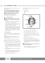
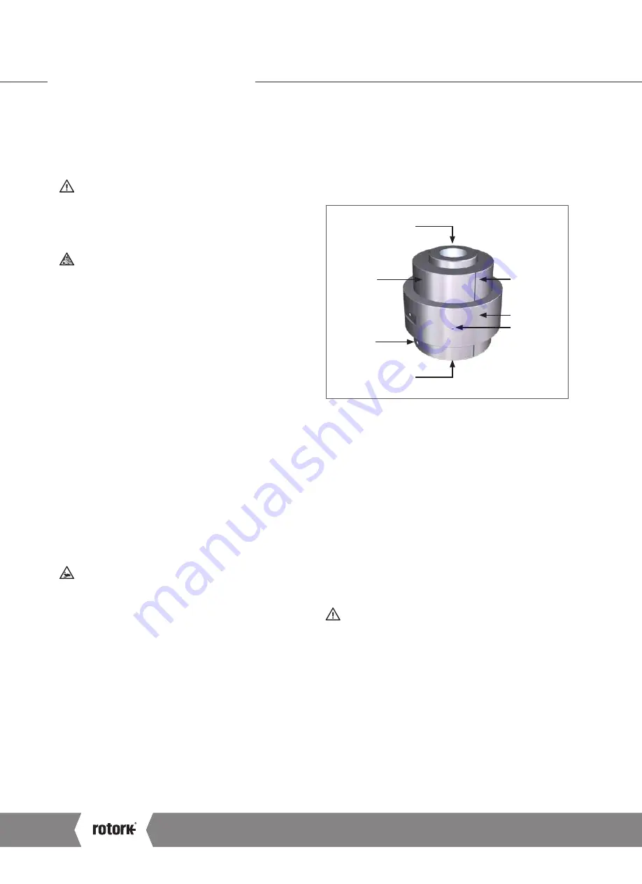
Standard coupling is constituted by the following standard
parts (see Fig 10.1):
• Actuator side joint
• Coupling clamp
• Ring
• Screws
Actuator side
Screw
Clamp
Ring
Screw
Clamp
Valve side
Fig 10.1 Standard coupling parts
• Fasten the actuator side joint on the actuator stem
• Fasten the valve side joint on the valve stem
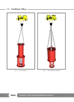
• Lift the actuator according to instructions in section 7.0
• Place the ring on the actuator stem holding it with the
hand and lower the actuator on the valve – the two joints
are now in touch
• Place the two clamps on the joints
• Lower the ring in position and fasten all the screws
• Tighten bolts or nuts between actuator spool piece and
valve top flange to the correct torque, in accordance with
the size and material characteristics of the bolts installed
by the customer
Support the actuator until fully installed and fixing
bolts are correctly tightened.
• Check for possible damage to the paint-work and repair if
necessary, according to painting specification
A4
US
US
A4
US
A4
US
A4
Summary of Contents for LP/S Series
Page 89: ...Keeping the World Flowing 89...

