14
Installation, Commissioning and Maintenance Manual
12.0 Operation
Actuator LP/S Type 1 and 2
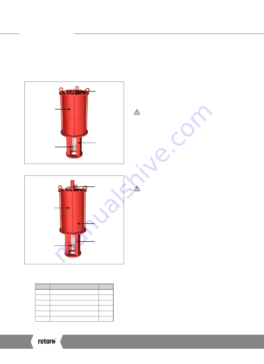
Main components of LP/S type 1 and type 2 actuator are
shown in Fig 12.3, Fig 12.4, Fig 12.5 and Fig 12.6.
Type 1 and type 2 differs in the spring package type installed,
but since the latter must not disassembled for safety reasons,
from a maintenance point of view can be regarded as identical.
1
4
5
2
Fig 12.3 LP/S type 1/type 2 without stop bolt main components
6
4
3
5
2
Fig 12.4 LP/S type 1/ type 2 with stop bolt main components
Table 2: LP/S type 1/type 2 Parts list
IT
DESCRIPTION
QTY
1
Plug
1
2
Spring cartridge
1
3
Cylinder tube
1
4
Spool piece
1
5
Valve connection
1
6
Stop bolt
1
12.3 Operating Description
Please refer to the Operating Diagram supplied for the
specific actuator.
12.4 Manual Override
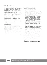
The LP series can be fitted with an emergency manual
override suitable to operate the actuator in the event of fluid
supply failure.
This device can be of mechanical screw type operated by
means of a handwheel, or of hydraulic type, with a hydraulic
cylinder operated using a hydraulic hand pump.
A maximum operating time of the manual override
of 24 hours, for maintenance or testing,
is recommended.
Note: The use of manual override is not recommended
in SIL applications. If it is necessary, strictly follow
instructions reported in the following paragraphs.
Before operating the mechanical manual override, ensure
that the cylinder is not pressurized and that the actuator is in
the fail position, then proceed as indicated in the following
paragraphs.
Important:
It is recommended to regularly clean the
“M” jackscrew and grease it afterwards.
Use a Molykote HSC PLUS grease.
After each use, verify that the manual override has
been disengaged before returning to remote operation.
The manual override can be of mechanical type or
hydraulic type.
A4
US
US
A4
US
A4
US
A4
Summary of Contents for LP/S Series
Page 89: ...Keeping the World Flowing 89...

