18
Installation, Commissioning and Maintenance Manual
12.0 Operation
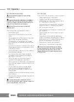
12.7 Linear Stroke Setting
Certain valves incorporate their own stops. For such
valves, it is recommended that the actuator stop bolt
positions coincide with the valve stop position.
Contact the valve manufacturer to set the valve
mechanical stops.
An incorrect setting of linear stroke could cause
damages to actuator, valve and/or to personnel.
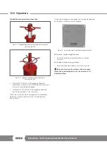
Single-acting actuator type 0,
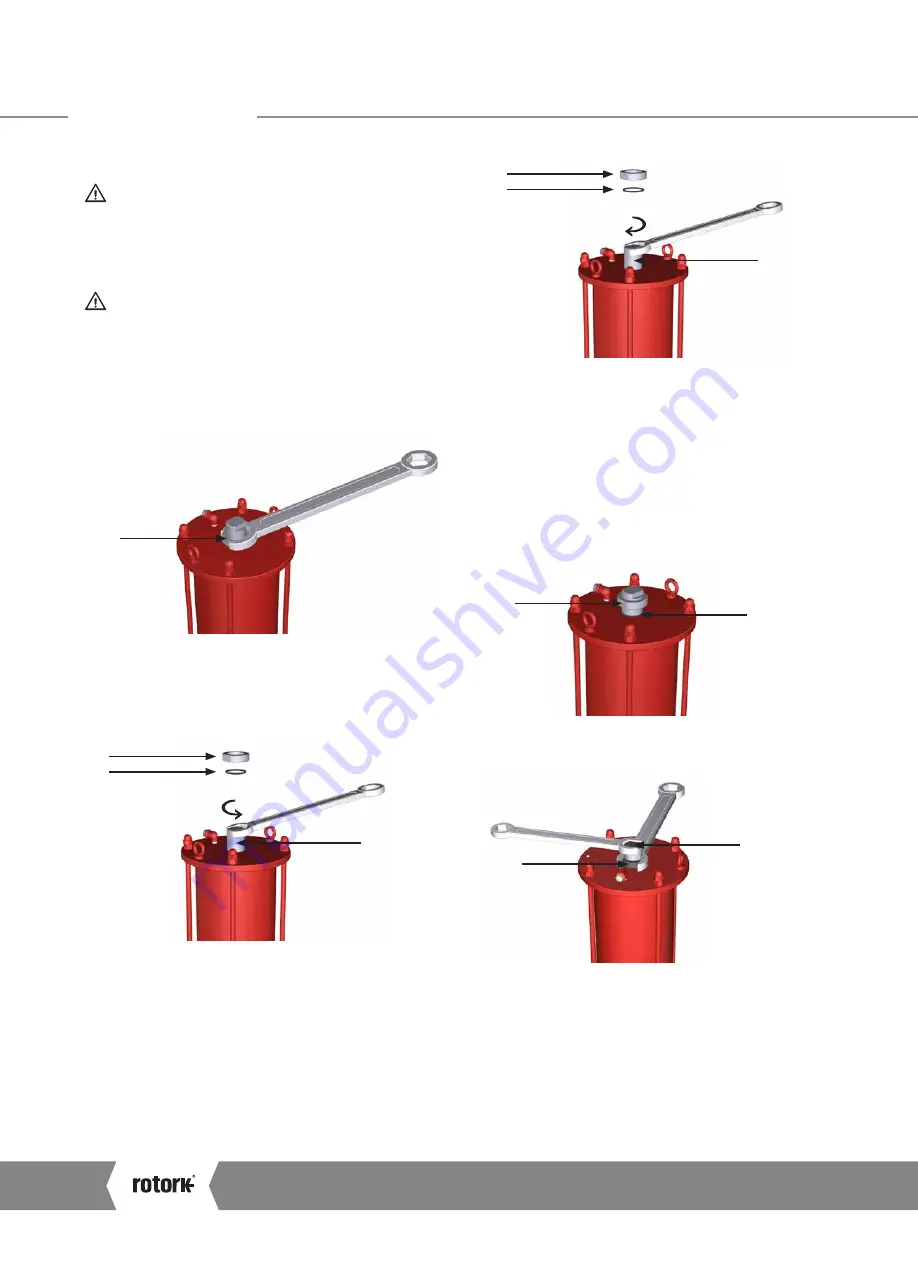
cylinder stop bolt setting
Perform the following operations as first setting.
Adjust the stop bolt located in the end flange of the cylinder
as follows:
1
A. Verify the absence of pressure
B. Loosen stop nut (1) and remove the O-ring (2)
C. Slowly pressurize the cylinder to detach stop bolt
from piston
1
2
3
D. With the help of a suitable size wrench, rotate the stop
bolt (3) counter clockwise to increase the angular stoke
E. Remove the pressure
F. Verify the newly obtained angular position with one stroke
G. Repeat operations A to F, until the desired angle is
obtained
1
2
3
H. With the help of a suitable size wrench, rotate the stop
bolt (3) clockwise to decrease the angular stoke
I. Remove the pressure
J. Verify the newly obtained angular position with one
stroke
K. Repeat operations H to J, until the desired angle is
obtained
L. Re-position the O-ring (2) between flange and the
stop nut (1)
2
1
M. Hold the stop bolt (3) with a wrench and carefully tighten
the stop nut (1)
1
3
A4
US
US
A4
US
A4
US
A4
Summary of Contents for LP/S Series
Page 89: ...Keeping the World Flowing 89...


