Modbus MFU Option Card Installation Manual
22 of 76
Publication PUB091-003-00_0119
4.5.1
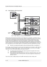
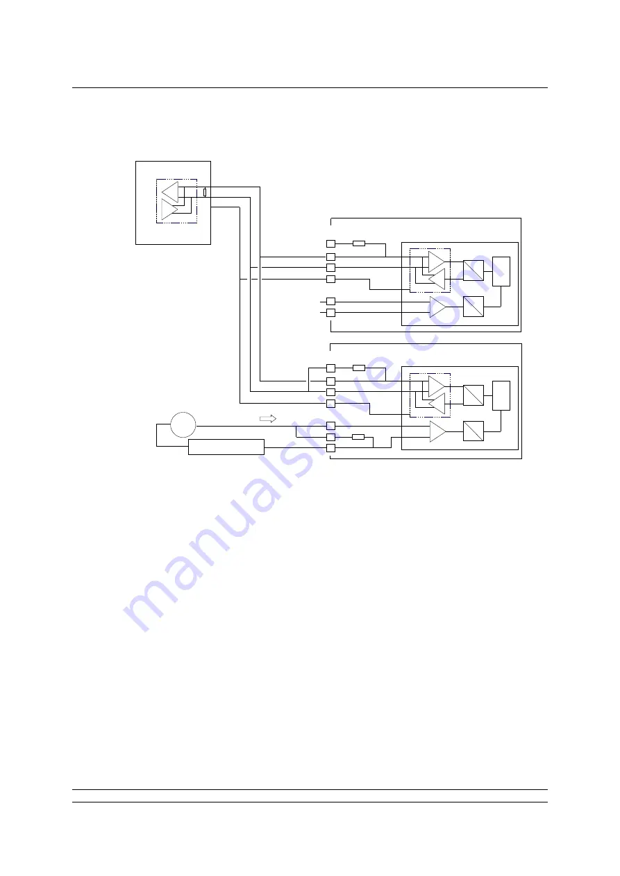
Single Highway with Analogue Input
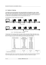
With the single channel option the actuator is connected to only one highway. An additional input is
provided for measuring and reporting an analogue variable to the Modbus controller. The connection
of the actuator to the highway uses terminals 1A and 1B. The terminal numbers depend on the
actuator type and are indicated on the actuator wiring diagram. The last actuator on the highway
should have the termination resistor connected by linking the highway 1B terminal to the Terminator
terminal. Take care to ensure that the correct polarity is observed on the data highway connection, all
the 1A terminals must be connected together on one data line and all the 1B terminals on the other.
Data line 1A is positive with respect to data line 1B when the MFU is transmitting a ‘1’.
If an analogue input is being used it is connected to the analogue input terminals. The MFU caters for
both current and voltage analogue signals. There is no power supply on the card for the analogue
transmitter and an external power supply must be used to power it.
For voltage inputs connect I/P A to the positive signal and analogue Common to the
negative signal from the transmitter
For current inputs connect I/P A to I/P B (to insert the conditioning resistor). The current
input positive is to I/P A and I/P B whilst the current input negative is connected to the
analogue Common.
There are no links or settings required on the MFU card when this version is being used.
Fig 16: Single H Analogue Input Connections
RS485
Highway
Analogue
Input
1B
1A
Terminator
Terminator
1A
1B
c
Common
Common
c
c
PLC/ Host
Tx
Actuator
Actuator
4-20 mA
+
I/P A
I/P B
Common
Tx Power Supply
-

