Modbus MFU Option Card Installation Manual
24 of 76
Publication PUB091-003-00_0119
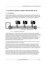
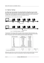
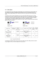
The actuator can be connected to two highways when redundant communication links are required.
The connection of the actuator to the highways uses terminals 1A and 1B for highway 1 and 2A and
2B for highway 2, the terminal numbers depend on the actuator type and are indicated on the actuator
wiring diagram. The last actuator on the highway should have the termination resistors connected by
linking Terminator terminal to the B terminal on the appropriate highway connection. Take care to
ensure that the correct polarity is observed on the connection on each data highway, all the 1A
terminals must be connected together on one data line and all the 1B terminals on the other for
highway 1, all the 2A terminals are connected together on one data line and all the 2B terminals on the
other for highway 2.
Data line A is positive with respect to data line B when the MFU is transmitting a ‘1’.
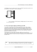
The dual channel MFU uses a single Modbus address common to both channels, so it is not possible
to run the same highway to both channels on the card.
One Modbus address for the card common for both channels.
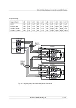
There are a number of jumper links on the Network Interface Card, which must be in the correct
position. These links determine the function of the card and when in the dual channel mode they must
be positioned as shown in the diagram. LK5 and LK6 may, in some cases, not be fitted. This is also
correct.
4.5.3
Single Highway with Internal Repeater
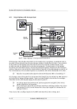
With this option a single highway passes through the Modbus Module and an internal repeater
regenerates the data signals. The input to output connection is also isolated and this then allows the
next section of cable to reach the maximum specified distance and the number of connected devices
on the section to be 32. Termination resistors will be required at all repeater connection points.
In addition to allowing for signal regeneration with the internal repeater it is also possible to connect
the last device on the network back to the PLC in a ring configuration. As each highway section is
isolated from its neighbours the ring topology affords a degree of redundancy. The PLC channels must
not be used simultaneously unless there is a section of the network that is broken.
Data line 1A is positive with respect to data line 1B when the MFU is transmitting a ‘1’.
There are a number of jumper links on the Network Interface Card that must be in the correct position
for the card to function as a single channel module. The repeater section is able to wait for the correct
period after transmitting data before changing to receive mode, this is important to ensure
communications on the highway is good. The time for the delay is set by jumpers on the mezzanine
and varies according to the data transmission speed chosen.
The internal repeater supports data speeds from 2,400 to 115,200 baud.

