Input and Output Signals
Publication PUB091-003-00_0119
27 of 76
5 THE ACTUATOR INPUT AND OUTPUT SIGNALS
The Modbus Module allows the actuator to be controlled by, and to report data to, a suitable host
device using Modbus RTU protocol. This section explains the data signals that are available for
exchange and their meaning in relation to the actuator functionality. The data locations used for the
Modbus registers and coils are given later in this manual.
This section also gives information on the other control inputs available for moving the actuator.
Inputs
are defined as signals originating at the actuator and fed back to the PLC over the
RS-485 network.
Outputs
are defined as signals originating at the PLC and operating the actuator
controls.
In general, the SI Pro and EH Pro actuators will behave in a similar manner to each other when
controlled by the MFU. The IQ Pro will be similar to the IQT Pro and the ROMpak will be similar to the
Q.
5.1 Control Outputs
The Modbus Module can be used to control the actuator and position the valve. The valve may be
moved fully closed, fully open or to an intermediate position. Additionally, the actuator can make the
valve adopt an Emergency Shut Down position. The actuator may also be operated from its local
controls or by hard wired direct contact inputs (in the case of the IQ and IQT the Auxiliary Input Mask
must be correctly set).
As well as controlling the actuator the MFU can also be used to operate 4 discrete output relays when
fitted to an IQ/IQT actuator with the relay card fitted.
The control commands have three potential sources:
Modbus RS-485 network generated commands
Actuator Local Controls
Direct contact input controls
The full list of commands is shown in the table. The actuator types show whether the command is
applicable to that actuator type.
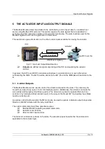
RS485 data highway
Outputs - Commands
Inputs - Feedback
PLC
Actuator
Fig 21: Input and Output Data Direction

