Modbus Communication
Publication PUB091-003-00_0119
40 of 76
6 MODBUS COMMUNICATION
6.1 Electrical Specification
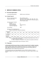
Line Electrical Specification:
RS-485, two-wire, half duplex
6.2 Outer Protocol
Modbus Transmission Mode
RTU (8 bit Binary data)
Supported Baud Rates
300, 600, 1k2, 2k4, 4k8, 9k6, 19k2, 38k4, 57k6, 115k2
(2k4, 4k8, 9k6, 19k2, 38k4, 57k6, 115k2 when using the
internal repeater option)
Number of bits per character
Start bits
1
Data bits (LSB first)
8
Parity (configurable)
Odd, Even, None
Stop bits (configurable)
1 or 2
Error checking
CRC
Message turn round time/delay time
Minimum period between request and response:
Data Speed
(Baud)
300
600
1k2
2k4
4k8
9k6
19k2
38k4
57k6
115k2
Turn Round
Time (ms)
188
100
60
40
28
24
20
20
20
20
Repeater
Delay
(μs)
NA
NA
NA
3.5
3.5
3.5
3.5
3.5
3.5
3.5
Note:
– In the Single Highway with Internal Repeater Modbus Module option there is a
propagation delay in the repeater.
– NA = not applicable, the repeater function cannot be used below 2,400 baud
.
Maximum period between request and response: 190 ms.
6.3 Repeaters
A single segment supports up to 32 nodes, one of which is usually the PLC. The addition of repeaters
allows the segment to be extended in length or increase the number of nodes connected or both. The
maximum lengths at different speeds are discussed in Section 4.2. The number of repeaters in a
single highway should be kept to a minimum, as this can seriously extend the delay between a
message being sent and the response arriving at the PLC.
The Single highway with Inbuilt Isolating Repeater version of the Modbus Module introduces
propagation delays as mentioned above. Care must be taken in any system design to allow for these
delays.

