Modbus MFU Option Card Installation Manual
46 of 76
Publication PUB091-003-00_0119
7.4 Broadcast Commands
Broadcast commands are only supported for specific registers, coils and commands.
Stop and ESD
Code 05 writes to coils 0 (Stop) and 3 (ESD) are supported for
address 0 broadcast.
Code 06 writes to register 5 (Actuator Digital Control) with values 0
(Stop) and 3 (ESD) are supported for address 0 broadcast.
7.5 Data Location Offsets
The locations given in the data base are those, which should appear in the messages as they are
transmitted on the Modbus link. Some host systems offset the addresses so far as the user is
concerned. In such cases the address programmed into the host would be different to those listed. All
data locations listed start from 0. Please check the host system documentation carefully to determine
if any offsets are required.
Typical Offsets are:
Function
Code
Offset to be added to
formulae result
1
1
2
10001
3
40001
4
30001
5
1
6
40001
7.6 Data Locations
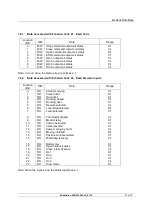
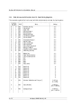
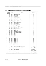
The data locations in the following tables are all numbered from 0. For a definition of the actuator
functions listed refer to Section 5. Not all the listed signals are available from every actuator type. For
the DO-1 to DO-4 options on IQ and IQT the relay output board must be fitted.
Note:
All data locations listed start from 0, it may be necessary to add an offset to match the
number required for the PLC.

