Contents
Publication PUB091-003-00_0119
5 of 76
12.1
Introduction ................................................................................................................... 69
12.2
Input and Output Signals .............................................................................................. 69
12.2.1
Control Outputs ............................................................................................................ 69
12.2.2
Digital Input Status Feedback ....................................................................................... 70
12.2.3
Analogue Input Status Feedback .................................................................................. 70
12.3
Modbus Communication ............................................................................................... 71
12.4
Modbus Data Base......................................................................................................... 71
12.4.1
Function Code Support ................................................................................................ 71
12.4.2
Broadcast Messages .................................................................................................... 71
12.4.3
Data Locations ............................................................................................................. 72
12.5
Configuration ................................................................................................................. 75
12.6
Records .......................................................................................................................... 75
Table of Figures
Fig 1:
The Modbus Module Option Card Actuator Compatibility....................................................7
Fig 2:
The Types of Modbus Module Mk2 Option Card ................................................................8
Fig 3:
The Modbus single channel NIC, showing the network connector. .....................................9
Fig 5:
The Interface Card (SI Pro and EH Pro actuators, Q is similar, see Section 3.2) ............... 10
Fig 6:
The Interface Card (IQ Pro and IQT Pro actuators) .......................................................... 10
Fig 8:
The MFU module profiled for the Q actuator .................................................................... 13
Fig 9:
The MFU located in a ROMpak actuator .......................................................................... 14
Fig 11:
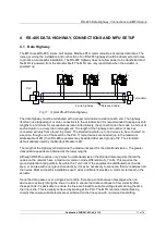
Typical RS-485 Data Highway ......................................................................................... 17
Fig 12:
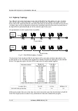
RS-485 Data Highway Topology ...................................................................................... 18
Fig 13:
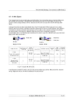
Typical RS-485 cable ....................................................................................................... 19
Fig 14:
Termination for RS-485 highway ...................................................................................... 20
Fig 15:
Termination for RS-485 highway in ROMpak actuators. The links are shown in the non-
terminated position. ......................................................................................................... 21
Fig 16:
Single H Analogue Input Connections ................................................................ 22
Fig 18:
Jumper Settings for Dual Highway Option ........................................................................ 23
Fig 17:
Dual Highway Connections .............................................................................................. 23
Fig 19:
Single Highway with Internal Repeater Connections......................................................... 25
Fig 20:
Jumper Settings for Single Highway with Internal Repeater Option................................... 26
Fig 21:
Input and Output Data Direction ....................................................................................... 27
Fig 24:
IQ and IQT relay outputs DO-1 to DO-4 ........................................................................... 32
Fig 25:
Modbus transaction format............................................................................................... 43
Fig 26:
Limited Range Position Control and Reporting ................................................................. 57
Fig 27:
Deadband and Hysteresis settings ................................................................................... 58
Fig 28:
Setting tool menu structure and MFU settable parameters ............................................... 64

