Configuration Registers
Publication PUB091-003-00_0119
59 of 76
8.1.4
Motion Inhibit Timer (Register11)
The Motion Inhibit Timer setting is the period that must elapse between consecutive starts of the
actuator motor when in positioning mode. The idle period will prevent the actuator motor from
exceeding its rated number of starts per hour.
In addition, when tuning the valve positioner the setting can be used to allow the plant dynamics to
stabilise between valve movements.
8.1.5
Auxiliary Input Mask (Register 12)
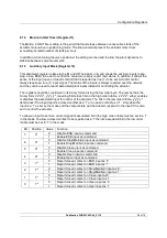
This parameter register relates to the IQ and IQT actuators only and allows the auxiliary inputs (open,
stop, close, ESD) to be set to control the actuator or simply report their status. In addition, it allows the
sense of the input (open or closed contact) that is reported as true (1) to be set. Actuator control
always requires a true (1) input signal. The status of the inputs is always reported over the network
and they can be used to report associated plant inputs instead of controlling the actuator.
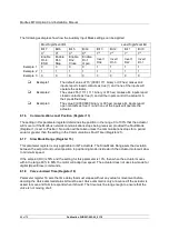
The register should be considered in its binary format using the low order byte. The number has the
binary form x
7
x
6
x
5
x
4
, y
3
y
2
y
1
y
0
, requiring 8 bits. Each bit in the high order nibble, x
7
x
6
x
5
x
4
, either enables
or disables the associated input for control of the actuator. The bits in the low order nibble, y
3
y
2
y
1
y
0
,
determines if the input reports a closed contact as a '1' or an open contact as a '1'. Only when the
input is a '1' as set by the mask and the contact state will the actuator respond to the input if it is also
set to control the actuator.
To allow an input to act as a control signal its associated bit in the high order nibble must be set to a '1'
in the mask. To allow a closed contact to be reported as a '1' then its associated bit in the low order
nibble must be set to '1' in the mask.
Bit
Position
Value
Function
7
X
7
0
Disable ESD input as command
1
Enable ESD input as command
6
X
6
0
Disable Stop/Maintain input as command
1
Enable Stop/Maintain input as command
5
X
5
0
Disable Close input as command
1
Enable Close input as command
4
X
4
0
Disable Open input as command
1
Enable Open input as command
3
Y
3
0
Report closed contact on ESD input as ‘0’
1
Report closed contact on ESD input as ‘1’
2
Y
2
0
Report closed contact on Stop/Maintain input as ‘0’
1
Report closed contact on Stop/Maintain input as ‘1’
1
Y
1
0
Report closed contact on Close input as’0’
1
Report closed contact on Close input as ‘1’
0
Y
0
0
Report closed contact on Open input as ‘0’
1
Report closed contact on Open input as ‘1’


