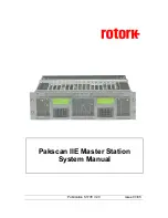
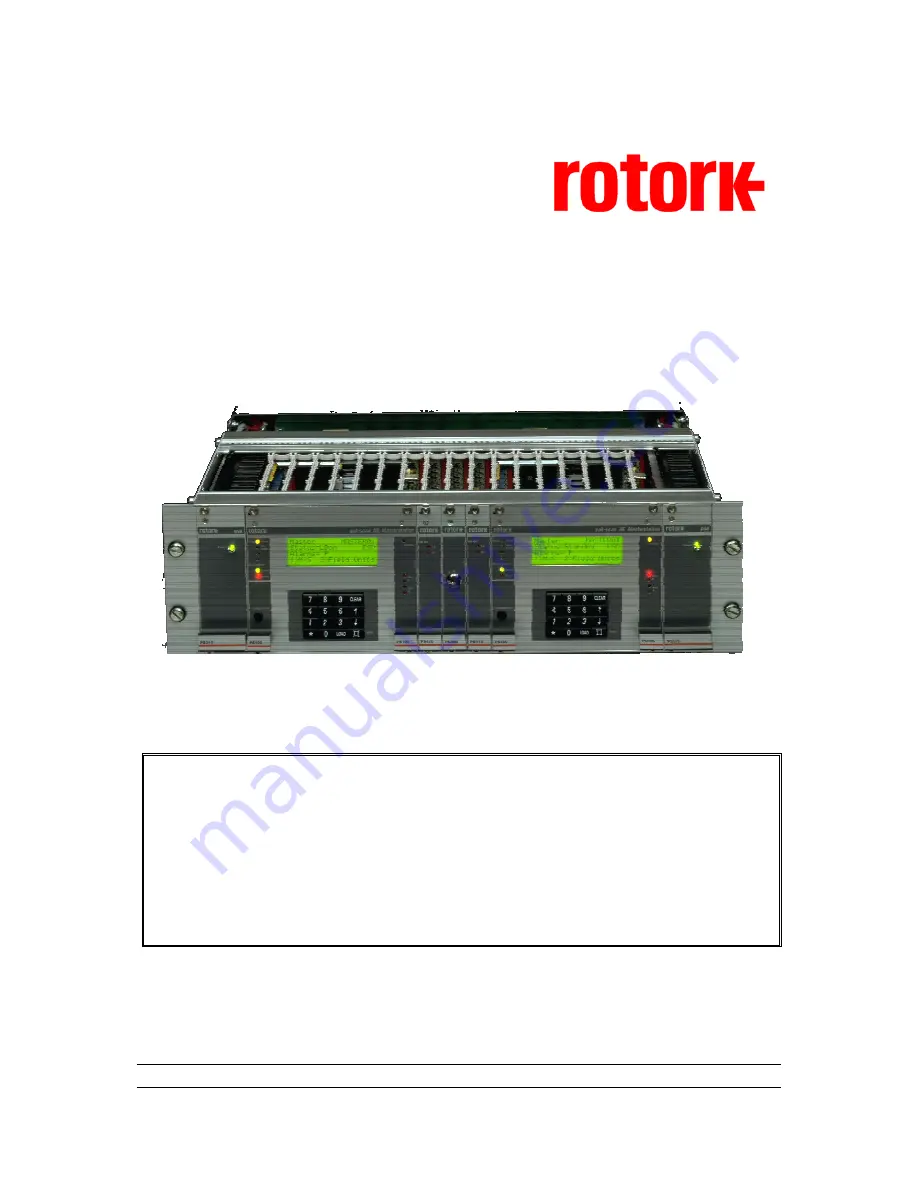
background image


Publication S177E V2.0 

Issue 03/05 


Pakscan IIE Master Station 

System Manual 


Summary of Contents for Pakscan IIE

Page 1: ...Publication S177E V2 0 Issue 03 05 Pakscan IIE Master Station System Manual...

Page 2: ...t not be reproduced without the written permission of Rotork Controls Ltd The name Rotork is a registered trademark Windows is a registered trademark by Microsoft Corporation Modbus is a registered tr...

Page 3: ...Fault Protection Loopback system 19 5 2 Current Loop Start Up Operations 19 5 2 1 Loop Configuration 20 5 2 2 Normal Running Operation 20 5 3 Modbus Serial and Ethernet Interfaces 21 5 4 Local User In...

Page 4: ...nus 51 8 8 1 Top Setup Menu 51 8 8 2 Port Setup Menus 52 8 8 2 1 Alarm Linkage 53 8 8 3 Data transfer to Standby Unit 54 8 8 4 Loop Setup Menu 55 8 8 4 1 Further Loop Options 56 8 8 5 Unit Address Set...

Page 5: ...RNET MODULE 87 12 1 Internal Connections 88 12 2 Connecting to the Ethernet Bridge 88 12 2 1 Local Ethernet Connection 89 12 2 2 Direct Ethernet Connection to a PC 89 12 2 2 1 Connection using Windows...

Page 6: ...reprogramming 112 13 4 4 Checking Host Communications 113 13 5 Final Checks 113 13 6 Commissioning Aids 114 14 MASTER STATION SOFTWARE VERSION 115 15 SET UP DATA RECORDS 117 15 1 Loop Map 118 16 TECH...

Page 7: ...Purpose field unit Master Slave The method of communication used on the field loop The master station controls the data exchange on the highway Node A single device address on the Pakscan loop RS485 T...

Page 8: ...Pakscan IIE System Manual 8 of 132 Publication S177E V2 0 Issue 03 05...

Page 9: ...is explained in section 13 If you have RS485 Converter units read section 11 carefully Ethernet connections are explained in section 12 Record the information about your system on data sheets such as...

Page 10: ...Pakscan IIE System Manual 10 of 132 Publication S177E V2 0 Issue 03 05 This page is intentionally blank...

Page 11: ...tible with all Pakscan II and IIE field units and setting tools The Pakscan IIE is equipped with either serial communication ports or Ethernet ports or both through which the master station can be con...

Page 12: ...Pakscan IIE System Manual 12 of 132 Publication S177E V2 0 Issue 03 05 This page is intentionally blank...

Page 13: ...or a particular application are in place When PS601 or PS602 Ethernet servers are fitted there will be links to the Port 1 or Port 2 connectors and these will not be available for host connections All...

Page 14: ...d For host computer communications either serial or Ethernet connections can be used The data format for information exchange is Modbus RTU for serial ports or Modbus TCP for Ethernet LAN connection T...

Page 15: ...ctronic hardware must be provided The ambient conditions should remain in the following bands at all times Temperature 10 30 degrees Centigrade Humidity Not to exceed 80 R H The equipment should not b...

Page 16: ...Pakscan IIE System Manual 16 of 132 Publication S177E V2 0 Issue 03 05 This page is intentionally blank...

Page 17: ...there is space for two These can be considered as two independent units The current loop is single fault tolerant and can withstand either an open circuit short circuit or ground connection fault and...

Page 18: ...output 4 2 Control and Indication The field units each report information to the master station that can be viewed on the integral LCD display or collected from the serial communication port of the m...

Page 19: ...the event of a loop fault With field units each side of a loop fault in loopback the system can still communicate with all field units by operating the system as 2 segments If there are 2 loop faults...

Page 20: ...has the facility to double the loop Baud rate If this facility is enabled via the Keypad the master station will issue a broadcast command to all the field units to get them to double the baud rate th...

Page 21: ...e master station itself Three separate registers of field unit alarms are maintained by the master station one for each serial or Ethernet port and one for the front panel display This ensures that al...

Page 22: ...Pakscan IIE System Manual 22 of 132 Publication S177E V2 0 Issue 03 05 This page is intentionally blank...

Page 23: ...and Display module contains a number of jumpers to set some of the parameters for the performance of the unit These are factory set and should generally not require adjustment at any time However ther...

Page 24: ...tted J11 ROM A15 jumper A15 Fitted J12 to J15 Digital input jumpers Un isolated Isolate channel Link 1 2 3 4 Link 2 3 J17 J18 RS485 termination jumpers J17 data J18 RTS Termination No Termination Fitt...

Page 25: ...stem then the pull apart resistors in that unit will already be connected J28 Battery Backup Link 2 3 connects the battery linking 1 2 isolates the battery If the battery is disabled or removed for an...

Page 26: ...If the rack does not contain a PS300 Switch module Link terminal 22 to 23 Link terminal 24 to 25 6 3 Display Screen Contrast On the front of the master station there is a multi turn potentiometer that...

Page 27: ...allowed for the rack to be withdrawn and placed safely when checks to the connections are required All connections are to the rear of the rack 7 2 Mains Power The individual master stations in the rac...

Page 28: ...arly to Port A In terminal 13 If a coloured pair red and blue is used this results in say the red wires being in terminals 12 and 16 with the blue wires in 13 and 15 The order is red blue blue red Fig...

Page 29: ...bly degrade the loop communications If your system includes a Signal Earth bar then connect the screen of one of the loop cables to this bar only Do not link the bar to the master station earth via th...

Page 30: ...ween screen and cores 5 Check the screen is continuous by measuring the resistance of the screen between the two ends 6 Check that the screen is isolated from earth by measuring the resistance between...

Page 31: ...re 2 Common 3 Resistance between Core 1 and 2 4 Total Resistance of both Cores should be the total of 1 and 2 5 Screen end to end Resistance 6 Cable to Screen Resistance should be high 7 Screen to Ear...

Page 32: ...Pakscan IIE System Manual 32 of 132 Publication S177E V2 0 Issue 03 05 This page is intentionally blank...

Page 33: ...D CLEAR Configuration Master MSTAG001 Status LB Off ESD 9 Alms P 1 M S 2 Field Units Field Alarm yellow Illuminates to indicate that a field alarm is present Standby Mode yellow Illuminates when the m...

Page 34: ...e LCD are decimal format Field Alarm New Alarm Addr Fault Host Active Masterstation Active Alarm PS100 PS100 Standby Port A Port B Contrast Menu 1 2 3 6 5 4 7 8 9 0 LOAD CLEAR Configuration Master MST...

Page 35: ...d by using the number keys on the control pad Commands and settings of the system require that the correct security level is chosen and when selected the PIN is entered All commands must be verified b...

Page 36: ...parate or Linked alarms for ports 2 Standby Setup Actions 1 Copy data to standby 2 Copy address to standby 3 Copy Master Station Tag to standby 3 Loop Shows current loop status and settings 1 Set spee...

Page 37: ...Block and Parameter screen 9 Alarms text 1 Next alarm if there is one For IQ Analogue field unit 1 Go to Block and Parameter screen 9 Alarms text 1 Next alarm if there is one For IQ Actuators 1 Open...

Page 38: ...testing for complete loop 4 LBbusy Find FCU s on B finding FCU s on port B 5 LBbusy Wait for LB 2 second wait for loopbacks to come on 6 LBbusy LBs off on A removing loopbacks from port A 7 LBbusy LBs...

Page 39: ...configure loop This should be used after a loop fault has been corrected Start or stop Configuration Mode A port selection screen appears to set the comms port to use with the MasterTools utility Hot...

Page 40: ...shows how many unacknowledged or current master station alarms there are The third line gives a full text description of each alarm in turn Pressing 1 displays the text string for the next alarm Pres...

Page 41: ...to use bearing in mind that the PC probably requires RS232 communications The hardware connection to the master station must still match the PC This means that for direct communication Port 2 the RS23...

Page 42: ...4 and loop driver software version 5206 034 The port activity flags flash to indicate when a message is received Rx or when a reply is transmitted Tx The centre of the fourth line contains a number th...

Page 43: ...of the last request func the Modbus function code of the last request addr the discrete bit or register number in the last request data the data field of the last request typically the number of poin...

Page 44: ...evice If Port 2 is set for Printer use then the diagnostic display will be changed from that shown in section 8 7 2 Modbus Port Diagnostic Displays to the one shown above The screen shows the followin...

Page 45: ...port Return wire fault fault detected in the return current path whilst the loop was running at double speed Doubling failed fault detected after loop assumed double speed If a fault occurs the Fault...

Page 46: ...ublication S177E V2 0 Issue 03 05 Commands available Go to FCU map screen Loop speed test only possible if loop is complete Field Unit address fault details only available if an address fault is prese...

Page 47: ...hough the system will only announce a Comms failure when 3 successive tries have failed to locate the field unit This counter therefore reflects the communications condition and can be used as an indi...

Page 48: ...done at speeds higher than the loop is currently running at The result of the test is displayed as a percentage success rate so that the user may have a degree of confidence in the performance with th...

Page 49: ...ess zero not permitted Line 3 shows the offending address Line 4 shows the position of the offending address or addresses The above example indicates that a field unit at address 10 was found at posit...

Page 50: ...transiently change to other values In addition they will show as below if there is a fault on the unit Signal status Condition OK The signal is good Hi The signal is stuck at logic 1 Lo The signal is...

Page 51: ...ngs Commands available Go to Port 1 setup page Go to Standby mode menu page Go to Loop options page Change unit address used in communications with host computers Go to FCU Tag names page Go to Date a...

Page 52: ...y mode This is usually set to Standby Passive preventing the port from generating replies to data requests If it is set to Standby Active then when this module side A or B is the standby unit the port...

Page 53: ...ach of the two ports This ensures that the different hosts see all the alarms When the alarms are linked accepting an alarm on one port accepts the alarm on all the other ports as well The status scre...

Page 54: ...y options and their current settings This option is only available on hot standby master stations and allows data to be automatically transferred from the main unit to the standby unit The default set...

Page 55: ...it will be reprogrammed into the field units immediately the loop is next reconfigured The Doubling Enable allows loop speed doubling to be enabled ON or disabled OFF If enabled the master station aut...

Page 56: ...The IQ DV Convert option can be used to ensure that 100 and 0 Desired Value outputs to the IQ actuators only is transformed into actions to make the actuator run to the fully open 100 and fully close...

Page 57: ...e Note that in some cases when using Pakscan Generic Modbus protocol settings the master station will respond to more than one address and the setting here is the Base address There is more informatio...

Page 58: ...e field unit address Edit field unit tag Go on to next FCU Go back to previous FCU Return to previous menu Editing a tag An arrow appears beneath the character being edited MSTAG001 Commands available...

Page 59: ...ernet alarm function when they are sent The date is displayed in the form Day Month Year The time is displayed in the form Hours Minutes Seconds using a 24 hour clock Commands available Set date Set t...

Page 60: ...lable Enables disables host port ESD input Enables disables keypad ESD input Enables disables hard wired ESD input terminals 32 and 33 Return to previous menu MENU 1 2 3 Note A hard wired input ESD wi...

Page 61: ...mmunication line is active If all serial communication links are inactive for 5 seconds then keypad commands can be entered provided the PIN is entered as with level 3 Commands available All changes r...

Page 62: ...t is in loopback Alarms key The letter is present if the alarm has occurred F FCU memory failure j Valve jammed P Power on reset o Valve obstructed C Communications failure e Motor running at end of t...

Page 63: ...que 2 More options This screen only appears for IQ and similar actuators it shows the current torque value and the status of the 4 auxiliary digital inputs on an IQ actuator The flag LoBat is displaye...

Page 64: ...t has been programmed with a torque filter factor of 000 then these 8 torque values are automatically returned to the master station once the actuator has travelled from one end of travel to the other...

Page 65: ...field unit is in loopback Alarms key The letter is present if the alarm has occurred F FCU memory failure j Valve jammed P Power on reset o Valve obstructed C Communications failure l Local stop pres...

Page 66: ...alarms code letters are the same as for an actuator field unit However only memory failure F comms failure C power on reset P and watchdog timer W are valid alarms As with the actuator page there is a...

Page 67: ...ent Option 5 prompts the user to enter a data value for the analogue output in the range 0 to 100 Commands available Go to next field unit Go to previous field unit Operate relay 1 Operate relay 2 Ope...

Page 68: ...he alarms code letters are the same as for an actuator field unit However only memory failure F comms failure C power on reset P and watchdog timer W are valid alarms As with the actuator page there i...

Page 69: ...t up if the field unit is not in communication with the master station FCUTAG01 Tag name 1 FCU address Alarm Comms Fail Alarm Address Fault FCU Fault 5 Block and parameter screen If the field unit has...

Page 70: ...as decimal numbers On entry of a parameter number the master station will send a message to the field unit to read the required data which will then be displayed On entry of new parameter data in a v...

Page 71: ...full text description of each alarm in turn Pressing 1 displays the text string for the next alarm Pressing 1 on the last alarm brings up the first alarm The following table shows the text displayed f...

Page 72: ...Pakscan IIE System Manual 72 of 132 Publication S177E V2 0 Issue 03 05 This page is intentionally blank...

Page 73: ...ameters no plant action will result The plant should only be returned to an operational state once it is certain that the parameters are correctly set or the programme operates correctly BEFORE COMMEN...

Page 74: ...do next Press 5 to select Setup Changes to the settings can only be made if the PIN is entered or the Access Level is set to 1 though the settings may be reviewed at any time The next screen displayed...

Page 75: ...ter station over the serial links then the setting should be Separate Once the settings are correct press MENU to install the settings and return to the previous page 9 3 Loop Data In section 7 4 the...

Page 76: ...oubling function will only operate successfully if all the field units are also upgraded to Pakscan IIE standards Once these three parameters are set they will only become active when this screen is l...

Page 77: ...dged whilst an unsuccessful entry prompts for a retry PIN s may be any number in the range 1000 to 9999 The default PIN on shipment is set to 1000 From the Top Setup Menu as shown section 8 8 1 select...

Page 78: ...Pakscan IIE System Manual 78 of 132 Publication S177E V2 0 Issue 03 05 This page is intentionally blank...

Page 79: ...ording to the host system requirements but be careful regarding the copy to standby settings in section 8 8 3 The default condition is to copy tags address and all parameter data between the two stati...

Page 80: ...of 2 wire loop connected directly to earth at one end only Actuator Terminals A B C Scr LK1 Ethernet RJ45 17 16 15 14 13 12 11 10 10 11 12 13 14 15 16 17 18 19 20 21 L N E Power Supply PS210 Processor...

Page 81: ...the master station that is actually in control of the 2 wire loop will issue commands to the loop So with a system using two communication links it is the responsibility of the Host computer to direct...

Page 82: ...ectronic components on the PS300 module and its function is solely to allow a unit to be removed for repair After a master station is replaced return the key to the normal position It may be necessary...

Page 83: ...ta The unit is designed to operate without the need for an enable signal from the host computer relying instead on line activity to enable the RS485 transmitter The two options require different insta...

Page 84: ...ate 2400 J3 1 2 RS485 data line bias resistor 3 4 RS485 data line bias resistor J4 1 2 RS485 data line termination resistor J5 1 2 RS485 control line bias resistor 3 4 RS485 control line bias resistor...

Page 85: ...multi drop RS485 serial link is essential if it is to work properly It should ideally be terminated with about 120 ohms at each end but NOT at each node and at one point only on the link there MUST b...

Page 86: ...re a balanced bi directional pair of signals which carry both transmitted and received data Note that the nomenclature used for the pair varies and or A and B are sometimes used The PS410 also support...

Page 87: ...diagnostic and control screens These screens are not available when Yokogawa or any other protocol is selected In order to view these screens it is necessary to connect a suitable PC with a web brows...

Page 88: ...2 Pin Function 1 RS485 Line A 2 RS485 Line B 3 Ground 4 Ground 5 RS232 transmit 6 RS232 receive 12 2 Connecting to the Ethernet Bridge The Ethernet connection uses a standard RJ45 connector an extensi...

Page 89: ...an IP Address Automatically Set PC connection properties to Static IP Address 12 2 2 1 Connection using Windows XP To set up a PC using Windows XP carry out the following steps Go to Start Settings Co...

Page 90: ...ff No Power Module Status Green Module is running in normal mode Orange During boot up Flashing Green Serial Packet Receive Serial Status Link Flashing Red Serial Packet Transmit Orange During boot up...

Page 91: ...dress 10 200 1 1 The user log in screen will appear once the connection is made In order to set up the final IP address the master station protocol to use between the Ethernet and the PS100 and so on...

Page 92: ...e settings between the bridge and the PS100 module to be set Modbus address The address must match the Modbus address set for the master station under section 8 8 5 The default is address 200 Mode The...

Page 93: ...r the two choices although the RJ12 connector is always used 12 4 2 Setting the User Fields for the Web Browser When the web browser feature is being used it is possible to set up several users each w...

Page 94: ...com Mobile Not implemented on Ethernet leave blank Alarm User Yes E mail alarm messages will be sent to the address entered No E mail messages are inhibited Yes User Level Read allows viewing of data...

Page 95: ...Sender A name used to identify this Pakscan system messages will be titled by this name to indicate which system it is Reply Path The address to send e mail reply messages to for this system Typically...

Page 96: ...nnection are made from the Network screen The LAN system administrator will normally provide the IP address and other settings The settings will depend on how the network has been set up It is usual t...

Page 97: ...Station Overview The overview screen is the first screen displayed after a successful log in The display will show either a Pakscan IIE or Pakscan IIS master station depending on the type of station...

Page 98: ...at care must be taken when doing so as the results can lead to loss of control or communication with the system The parameters that can be altered are described in detail in section 8 8 of this manual...

Page 99: ...8 7 4 Note Do not alter the Host Port Configuration for the serial port connected to the Pakscan Ethernet module If this is changed communication between the PS600 and PS100 will be disrupted The cor...

Page 100: ...the status of the field cable is shown and the location of any fault that is present together with the nature of the fault Any device in loopback is indicated in the table by shading the cells The loo...

Page 101: ...tuator at that address The basic status of the actuator is shown on the left and the picture on the right shows the type of actuator The valve may be opened or closed or set to an intermediate positio...

Page 102: ...be accepted from this screen Alarms are latched until they are accepted and once accepted the indication will return to normal if the alarm condition no longer exists Clicking the Alarm Accept button...

Page 103: ...imilar to that shown above Click on Continue to move to the next screen This shows a list of all the field units their tag names and a button to write new names In addition there is an FCU Parameter b...

Page 104: ...meter button leads to the individual field unit parameter screen Every field unit has a number of configurable parameter settings that determine its operation in the network If these are not correctly...

Page 105: ...xamined including those relating to the operation on the network Note Information about the field unit settings can be seen in the parameters listed but alterations cannot be made from this connection...

Page 106: ...Pakscan IIE System Manual 106 of 132 Publication S177E V2 0 Issue 03 05 This page is intentionally blank...

Page 107: ...tate once the loop is operating correctly BEFORE YOU START Ensure all the measurements and checks described I section 7 4 have been carried out When the loop resistance and capacitance was measured th...

Page 108: ...ort B disconnected This time make sure that all the field units except the one furthest away are powered off Select the Master Station Status screen go to the Master Station Commands screen and Reset...

Page 109: ...ect the address for the powered on field unit by using the Up or Down arrow key The FCU status screen as illustrated in section 8 9 1 will show if communication is established Now switch on the next n...

Page 110: ...isconnect the two wires at Port A Re configure the loop With the loop running turn Port B s potentiometer RV102 clockwise until the B LED on the door just goes out Then turn the potentiometer back sli...

Page 111: ...will come on when there is a complete current circuit If it does not come on there is a break near the Port A end The Port A LED then flickers as field units are found and their loopbacks removed If t...

Page 112: ...communication fails 3 times in succession and it may be set to zero by the Clear button In most systems communication errors will occur due to interference from associated plant The main thing is tha...

Page 113: ...button will update the screen to the latest information Successive screen interrogations will reveal all the Modbus messages being sent to the master station Pressing the Clear button will reset the...

Page 114: ...d unit via the 2 wire interface This requires the disconnection of the field unit from a live loop The Field Test Unit can also program various field unit parameters The second device is the Master St...

Page 115: ...reference The serial number will be found on a data label on the rear of the unit The master station type includes a code as follows S W Type X X X X 01 Pakscan IIE system 1 Single Unit 2 Hot Standby...

Page 116: ...Pakscan IIE System Manual 116 of 132 Publication S177E V2 0 Issue 03 05 This page is intentionally blank...

Page 117: ...ss Host Master Station IP Address Ethern t Protocol Selected on Port 1 Baud Rate Parity Protocol Selected on Port 2 Baud Rate Parity Alarms Linked Separate Security PIN Access Level Loop Baud Rate Hig...

Page 118: ...50 21 51 22 52 23 53 24 54 25 55 26 56 27 57 28 58 29 59 30 60 For each field unit record the settings made for the performance of the field unit Field units are of 3 basic types IQ Actuator Actuator...

Page 119: ...ral Actuator Type Tag FCU Type Address Baud Rate Analogue Update Time Analogue deviation Threshold Motion Inhibit Time Motion Inhibit Deadband General Purpose Field Units Actuator Mode Actuator Type T...

Page 120: ...Pakscan IIE System Manual 120 of 132 Publication S177E V2 0 Issue 03 05 This page is intentionally blank...

Page 121: ...l Modbus RTU Format Asynchronous Baud rate 1200 2400 4800 9600 and 19200 Parity Odd Even None or Always 0 Stop Bits 1 Host Communications Ethernet option Connector RJ45 Protocol Modbus TCP Loop Connec...

Page 122: ...0 o C Capacitance pF m 0 5 solid 36 8 km 115 pF m 0 5 flexible 39 7 km 115 pF m 1 0 solid 18 4 km 115 pF m 1 5 stranded 12 3 km 115 pF m Maximum Loop Distances The cable resistance and capacitance mus...

Page 123: ...e table The times assume that only one field unit has data to report during the scan Scan Time seconds Baud Rate No of FCU 2400 1200 600 300 110 60 0 39 0 77 1 54 3 08 8 4 120 0 89 1 77 3 54 7 08 19 3...

Page 124: ...Fitted Main 3 Terminals 18 to 21 are only used as described on the A side 4 The alarm contacts shown terminals 1 to 9 are shown in the powered off state 5 Terminals 1 to 3 show the alarm contact stat...

Page 125: ...or and uses RS232 hardware protocol This port can be used as a data port or for connection to a serial printer The connections are shown in the table The CTS signal is an input to the master station t...

Page 126: ...5 highway Ethernet Port The Ethernet port uses a standard RJ45 socket for communication and is normally connected to a switch by a straight cable If the port is used to connect directly to a PC then a...

Page 127: ...hermostat Tripped 6 Local Stop Pressed 7 Stop Start Failure 8 Valve Jammed 9 Valve Obstructed 10 Manual Open 11 Manual Close 12 Manual Opening 13 Manual Closing 14 Motor Running End Of Travel 15 Not a...

Page 128: ...9 kg PORT 1 RS485 PORT 2 RS232 FIELD CONNECTIONS PORT 3 PORT 4 RS485 PORT EXP PORT 3 PORT 4 RS485 PORT EXP PORT 1 RS485 PORT 2 RS232 FIELD CONNECTIONS MAINS INPUT 90 264 Vac FUSE 1A MAINS INPUT 90 26...

Page 129: ...uch excess is applied the product should be returned to Rotork or otherwise checked by a competent person before re use even if no damage is immediately evident Use only the specified fuse type and ra...

Page 130: ...s should only be used for statistical purposes These predictions are only valid if the maintenance procedures and maintenance intervals stated in Rotork documentation are observed Environmental Produc...

Page 131: ...131 of 132 Publication S177E V2 0 Issue 12 04 This page is intentionally blank...

Page 132: ...3 200 Fax 44 0 1225 333 467 e mail mail rotork co uk USA Head Office Rotork Controls Inc 675 Mile Crossing Blvd Rochester New York 14624 USA Tel 1 716 328 1550 Fax 1 716 328 5848 e mail info rotork co...

Reviews: