Profibus DP Mk2 Option Card Installation Manual
26 of 84
Publication PUB088-005-00_1017
4.5 Cable Types
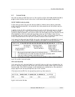
The network must be connected using a suitable cable for Profibus DP applications. Two conductors
plus a shield are required and there is a Profibus specification for the cable.
Amongst the cable manufacturers Belden have the PVC jacketed single pair 2 core cable, which
meets the minimum requirement. Information on Belden cable may be found on the Belden web site
(www.belden.com).
PVC sheath, usually coloured purple Tinned copper screen Signal wires
Red is positive, ‘B’
Gre
en is negative, ‘A’
Typical Profibus DP Cable Specification
Impedance
135 up to 165 ohm at a frequency of 3 to 20 MHz
Cable capacitance
<30 pF per metre
Core diameter
>0.34 mm2 (corresponds to AWG 22)
Cable type
Twisted pair cable, 1x2 or 2x2 or 1x4 lines
Resistance
<110 ohm per km
Signal attenuation
Max 9dB over total length of line section
Shielding
Copper shielding braid or shielding braid and shielding foil
The terminals to which the wires connect in the each actuator type will be different and the actuator
wiring diagrams must be consulted to establish the connections.
4.6 Termination Network
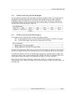
In order to operate correctly all Profibus segments must be terminated at each end in an active
network termination circuit. The Profibus DP (Mk2) card includes the necessary components to allow
an active termination to be connected. In order to connect the termination network it is necessary to
add a link to the actuator terminals and also fit two internal jumpers to the circuit card, per highway.
See section 4.7 below for details where to fit the links in the various options of the card.
Fig 18: Typical Profibus DP cable specifications
Fig 19: Termination for Profibus highway
VP
(5V)
390
DGND
(0V)
390
220
Link
TxD/RxD-N
TxD/RxD-P
L2
L1
B
A


