background image

Input and Output Signals 


Publication PUB088-005-00_1017  

39 of 84   

F

ou
nd
ati
on
 F

iel

db
us
 FF

-01
 In
s

tal
lat

io

n m

an
u

al


5.1.2 

Profibus Control using the ACTCON Register 

A single register is provided to allow the digital control of the actuator. Writing to the individual bits in 
the register causes the actuator to open, close, stop, ESD, adopt Positioning mode or perform a 
Partial Stroke and at the same time cancels any other command set. The bit written changes any 
output states already set to the new value. Only one bit may be written in a command. If more than 
one bit is set then the whole register is ignored. 
 

ACTCON Register  

Bit 6 - 15 

Bit 5 

Bit 4 

Bit 3 

Bit 2 

Bit 1 

Bit 0 

Reserved


Part Stroke 

Position 

Enable 

ESD 

Open 

Close 

Stop 


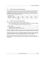
5.1.3 

Profibus Control using the POS_DV register 

The analogue position control function requires two registers to be set.  


A desired position value to move the valve to should be placed in the POS_DV register 


The ACTCON register must be set to Position mode ( 0010 hex) 


POS_DV Register  

Register value: 0 to 1000 (0 to 3E8) 

Position demand: 0.0% to 100.0% of valve travel 

 
When the ACTCON register with Position mode set is sent, the actuator will position to the value set in 
the POS_DV register and any other commands that are currently being carried out will be cancelled. 
 
If the POS_DV register is set to 0% and limited range positioning is not being used the actuator will 
operate as though a ‘close’ command had been sent. Similarly if the POS_DV register is set to 100% 
under thes

e conditions the actuator will interpret the instruction as an ‘open’ command.  

 
Note that when limited range positioning is used and the actuator is in the fully closed position a 
POS_DV value of 0%, or when the actuator is in the fully open position a POS_DV value of 100%, are 
not acted upon. 


Summary of Contents for Profibus Modbus Module Mk2

Page 1: ...Publication PUB088 005 00_1017 Profibus Actuator Control Profibus DP Option Card Installation Manual...

Page 2: ...Interface Card software version M207 IQ M304 CVA V1 08 ROMPAK V1 01 or newer Note 3 The Profibus DP Module MK2 described in this manual is suitable for inclusion in Rotork IQ IQT CVA ROMPAK Skil and Q...

Page 3: ...e Highway System 20 4 3 Redundant Systems Simple Redundancy 21 4 3 1 Flying Redundancy Slave to Master Connection 22 4 3 2 System Redundancy Slave to Master Connection 23 4 4 Redundant Systems RedCom...

Page 4: ...ammed Time Parameter 8 63 7 1 7 Watchdog Timeout Parameter 9 63 7 1 8 Action on Loss of Comms Parameter 10 63 7 1 9 Comms Lost Position Parameter 11 63 7 1 10 Comms Fault Timer Parameter 12 64 7 1 11...

Page 5: ...for a device from one manufacturer to interact with that of another manufacturer on a fieldbus network without loss of functionality Master Slave The method of communication used by the Profibus DP Mo...

Page 6: ...es Profibus Guideline 2 112 Installation Guideline for Profibus DP FMS Profibus Guideline 2 212 Specification Slave Redundancy Profibus Guideline 2 152 Specification for Profibus Device Description an...

Page 7: ...allows for system maintenance and asset management tools to be used Electronic data sheets are available in GSD EDD and DTM formats Profibus DP V0 and DP V1 compliant RedCom redundancy included both...

Page 8: ...cessary extra messages for RedCom systems PLCs that cannot accept the extended diagnostic messages from RedCom slaves should use the Simple Dual channel card The reporting of RedCom extended diagnosti...

Page 9: ...ing IQ range Skil EH and Q All the connectors are polarised to prevent incorrect insertion Network Interface Card NIC This small printed circuit board carries the Profibus DP RS485 highway connections...

Page 10: ...d and passing this data to the Network Interface card For the IQ IQT it is used simply for physical connection to the main card The primary connection to the actuator circuits is by a multi pin connec...

Page 11: ...rity The Profibus DP fieldbus data highway connections are fully isolated from the actuator electronics 2 3 Operation and Storage The PFU is designed to be stored in the actuator and operated within t...

Page 12: ...Profibus DP Mk2 Option Card Installation Manual 12 of 84 Publication PUB088 005 00_1017 This page is intentionally blank...

Page 13: ...opriate connectors to match the IQ IQT actuator The illustration below shows the IQ IQT version of the PFU The links for the bias resistors are shown in the not terminated position With the IQ IQT act...

Page 14: ...r is the ability to report the status of the remote control inputs as Digital Inputs The following table shows the wiring harnesses that must be fitted and the function of each loom for the Q range ac...

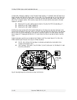
Page 15: ...rd slot inside the CVA electrical housing on the underside of the Main PCB assembly SK3 is the connection to the Profibus Fieldbus Data Highway The PFU in the CVA must be enabled This would usually be...

Page 16: ...he connection to the Profibus Data Highway this is connected to SK23 on the main PCB assembly via an internal loom The user wires the Profibus connections to the main PCB assembly at the terminal bloc...

Page 17: ...ed position With the Skil EH actuator the remote inputs are always present they are conditioned by the PFU and there is an option to include Digital Outputs from relay contacts The following table des...

Page 18: ...ecessary wiring looms must be added to the internal wiring harness of the actuator The actuator wiring diagram shows the connectors and harnesses used The wiring harnesses are fitted inside the actuat...

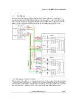
Page 19: ...e maximum addressable of 126 then repeaters may be added as required Up to 9 repeaters can be used on a single highway provided no more than 4 are between any two devices Data Rate Baud 9600 19200 45...

Page 20: ...e used so that when the actuator is switched off the bus performance is not affected Maximum number of devices participating in the exchange of data 127 addresses from 0 to 126 0 is usually the PLC Ma...

Page 21: ...orts its status on the highway There are a number of PLC systems including older PLCs that do not have the ability to use the RedCom system and as a consequence they are likely to report errors when c...

Page 22: ...channels using a 32 second switch over time until one channel receives PLC messages In the event of a failure of the Primary channel the Backup automatically changes to use the Primary address Hence f...

Page 23: ...it reaches its maximum of 32 seconds It will continue to switch channels using a 32 second switch over time until one channel receives PLC messages In the event of a failure of the Primary channel the...

Page 24: ...setup using only a single cable but with two Profibus connections is termed FR or Flying Redundancy With FR systems there are two Profibus interfaces on the slave but only one slave so protection aga...

Page 25: ...nfigure the Profibus card to be Simple or disable the PLC s diagnostics package that is looking at the extended diagnostics A RedCom Dual Channel card can be altered to a Simple Dual Channel card or v...

Page 26: ...2x2 or 1x4 lines Resistance 110 ohm per km Signal attenuation Max 9dB over total length of line section Shielding Copper shielding braid or shielding braid and shielding foil The terminals to which t...

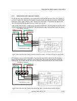
Page 27: ...is connected to only one highway and an additional input is provided for measuring and reporting an analogue variable The connection of the actuator to the highway uses terminals A and B in and out te...

Page 28: ...positive signal and analogue Common to the negative signal from the transmitter For current inputs connect I P A to I P B to insert the conditioning resistor The current input positive is to I P A an...

Page 29: ...at the end of the highway The choice between Simple and RedCom compliant redundancy does not affect the connection options The connection of the actuator to the highway uses terminals 1A 1B in and out...

Page 30: ...tions default to System Redundancy this allows two separate highways to be used When the RedCom compliant version is used the card uses RedCom extensions to the standard DP V1 protocol to permit redun...

Page 31: ...the disconnect module is powered and ensures that the Profibus signals are passed to the actuator as shown below B In B Out A Out A In Single disconnect module A In B Out A Out B In Field Network con...

Page 32: ...rofibus disconnect module has to be removed from the actuator for instance to replace the actuator the power must be removed from it and the network and the necessary hazardous area permits to work mu...

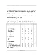
Page 33: ...ntrol inputs available for moving the actuator Outputs are defined as signals originating at the PLC and operating the actuator controls Inputs are defined as signals originating at the actuator and f...

Page 34: ...ut relays when fitted to an IQ IQT actuator with the extra relay indication board fitted The control commands have three potential sources Profibus DP network generated commands Actuator Local Control...

Page 35: ...witch is reached when the torque exceeds the value set and the close limit switch has been reached or a new command is sent over the network Stop With no other command present this digital command cau...

Page 36: ...ernal relays on the extra relay indication board in an IQ or IQT actuator These outputs are referred to as S5 S8 in the standard actuator documentation when there is no Profibus DP Module in the actua...

Page 37: ...nd will re assert itself In the case of the hard wired input for ESD this can be configured either as an ESD HW_DI 4 signal or as a Profibus Command Inhibit to prevent network control signals from mov...

Page 38: ...ibus ESD Profibus Open Profibus Position Profibus Stop Mechanically interlocked to prevent both at the same time The action depends on the Actuator Control Priority setting Only one Profibus command i...

Page 39: ...equires two registers to be set A desired position value to move the valve to should be placed in the POS_DV register The ACTCON register must be set to Position mode 0010 hex POS_DV Register Register...

Page 40: ...r corresponding to the desired port number to go to In addition during parameterisation the number of ports and number of active ports must be set PORTCM Register Register value 1 to 10 1 to A hex Pos...

Page 41: ...A2 6 Register 0 Bit 14 Position Control Enabled IDATA2 7 Register 0 Bit 15 Watchdog Recovery IDATA3 0 Register 1 Bit 0 Battery Low IDATA3 1 Register 1 Bit 1 Open Interlock input IDATA3 2 Register 1 Bi...

Page 42: ...r three position remote local stop local selector is in the Remote position The selector must be in this position for Profibus control to be permitted Local Stop The actuator three position selector p...

Page 43: ...d This bit will be true 1 if the actuator is stationary at the end of travel and fails to move away from the seat of the valve when a network command requests it to do so The actuator will trip on exc...

Page 44: ...y is monitored and should it fall below a critical level this signal will become true 1 The battery is used to power the circuits used to keep track of the valve position when the actuator mains power...

Page 45: ...iliary Input Mask parameter which determines whether the bit is reported as true 1 for a closed contact or an open contact and whether the input controls the actuator or not Note that the input is alw...

Page 46: ...r to perform a partial stroke of the valve the starting position is specified as either the open limit or the close limit If the actuator is commanded to perform a partial stroke when it is not in the...

Page 47: ...card When reporting as 0 the bit indicates that one address is being used On a single channel card only one address is permitted On a dual channel card a single address is used when two Profibus DP h...

Page 48: ...us DP Module Mk2 Torque The currently developed torque value is reported as an Integer Value in the range 0 to 120 0 78 hex representing the percentage of actuator rated torque generated Valve Positio...

Page 49: ...communication the card firstly enters parameterisation mode and adjusts the card parameters according to the GSD file settings Next the card enters configuration mode where the configuration settings...

Page 50: ...Profibus DP Mk2 Option Card Installation Manual 50 of 84 Publication PUB088 005 00_1017 This page is intentionally blank...

Page 51: ...r and the IQ setting tool For all actuator variants the address can be set over the highway using a Class 2 master Baud Rate This is selected by the PLC Slave Configuration One of the 10 configuration...

Page 52: ...file values or by using a parameterisation utility such as FDT or PDM Redundancy The default setting for redundancy is SR mode In SR mode there are two highways and a redundantly configured PLC The t...

Page 53: ...SR Mode Both channels have the same slave address When the card is powered on Channel 1 will be the Primary channel After power up the card will seek a master to communicate with by alternating the ch...

Page 54: ...g a different address When using either type of dual channel card in FR mode the following must be set up Address The two channels have address offset by 64 Setting the base address will set the offse...

Page 55: ...nnel 1 will be the Primary channel After power up the card will seek a master to communicate with by alternating the channel 1 and 2 between Primary and Secondary mode The switch over time increases w...

Page 56: ...If a correct response is received a Check_Config telegram is sent 6 The response should be a Short Ack message 7 If this is correct a DIAG_req telegram is sent 8 The response should be a DIAG_res with...

Page 57: ...ituation If the PFU is unable to communicate to the main board the data which is sent in data exchange communication is potentially stale not current Therefore if the static diagnostic bit is raised t...

Page 58: ...Profibus DP Mk2 Option Card Installation Manual 58 of 84 Publication PUB088 005 00_1017 This page is intentionally blank...

Page 59: ...an be altered by using the infra red communications link and the setting tool All of them can be altered by the values in the GSD file or by a V1 communication tool such as PDM or FDT when the appropr...

Page 60: ...dCom 1 0 0000 hex 16 Part Stroke position 1 99 0001 0063 hex 90 005A hex 17 Part Stroke Limit and timeout Bit 15 is 0 for close limit and 1 for open limit Bits 0 14 are time values in seconds for time...

Page 61: ...the full stroke which will now be used for the limited stroke 0 and 100 values Not supported by CVA 7 1 2 Deadband and Hysteresis Parameter 3 and 4 When using position control by sending a value to th...

Page 62: ...ore the motor stops Not supported by CVA 7 1 3 Slow Mode Range Parameter 5 This parameter register is only applicable to IQT actuators The Slow Mode Range sets the deviation between the setpoint and c...

Page 63: ...sor the Watchdog Recovery data bit is set The data bit will automatically reset to 0 after the time period set in this parameter register 7 1 8 Action on Loss of Comms Parameter 10 This parameter is u...

Page 64: ...ed input for control of the actuator The bits in the low order nibble y3y2y1y0 determines if the input reports a closed contact as a 1 or an open contact as a 1 Only when the input is a 1 as set by th...

Page 65: ...tuator in their predefined way Example 3 The value 0 0000 0000 binary or 00 hex makes all 4 inputs report open contacts as true 1 and none of the inputs will operate the actuator 7 1 12 ESD DI 4 Net D...

Page 66: ...Stroke Position Parameter 16 This parameter sets the position to travel to when a Partial Stroke command is carried out The partial stroke can be initiated from either the open or the closed position...

Page 67: ...te W to the parameter using one of these utilities Parameter No Data Read Write Value Range Default Value 20 Actuator Tag data R W 12 byte 0 21 MIC software version R 4 byte e g M204 22 PNIC software...

Page 68: ...20 0 to 0078 h 0 61 Torque at 60 close direction R 0 120 0 to 0078 h 0 62 Torque at 70 close direction R 0 120 0 to 0078 h 0 63 Torque at 80 close direction R 0 120 0 to 0078 h 0 64 Torque at 90 close...

Page 69: ...eak contact 1 ESD make contact 0000 99 ESD bypasses the actuator interlocks R W 0 bypass disabled 1 bypass enabled 0000 100 ESD bypasses the Thermostat trip R W 0 bypass disabled 1 bypass enabled 0000...

Page 70: ...wer cycle If the actuator is switched off then back on the standard Profibus start up routine will impose the parameter values set in the GSD file for the device This parameter allows the card to be s...

Page 71: ...rameter 38 is used to set up the actuator to match the multiport valve The value in this register sets the number of ports that will be used up to the maximum of 10 If the valve has 6 ports but only 4...

Page 72: ...tuator is moving from closed to open and reaches a particular position x The parameters contain 11 values of torque generated in 10 position increments between 0 and 100 of valve travel Torque at x wh...

Page 73: ...tating indicates centre column rotation 0A Motor Stalled indicates the motor has stalled 0B Battery low indicates that the battery is low 0C Hand operation indicates that the centre column is rotating...

Page 74: ...p Parameter 101 This parameter selects whether an active ESD will still operate the actuator even if it is in Local Stop 7 2 15 Interlock enable Parameter 102 This parameter indicates if the interlock...

Page 75: ...art to be active when the actuator is travelling in the close direction 7 2 28 Language used Parameter 109 This parameter indicates if the language used in the local actuator display is the standard E...

Page 76: ...Profibus DP Mk2 Option Card Installation Manual 76 of 84 Publication PUB088 005 00_1017 This page is intentionally blank...

Page 77: ...the default value is 126 8 1 Using a Network Configuration Tool The Profibus DP Module caters for two configuration tools FDT and PDM 8 1 1 FDT Field Device Tool This utility uses DTM device descript...

Page 78: ...lity uses EDD device description files and the PDM programme from Siemens A typical configuration screen is illustrated below As with FDT the parameters and the control and review of actuator informat...

Page 79: ...nd using the other configuration tools Parameter No Menu Code Description Range Default Value 1 FL Limited Range Position Minimum 0 100 0 2 FH Limited Range Position Maximum 0 100 100 3 Fd Deadband 0...

Page 80: ...e Password CR R1 R2 R3 R4 A1 A2 A3 A4 A5 A6 A7 A8 A9 ESD action ESD contact type ESD t stat bypass ESD override interlocks ESD override local stop Maintained local control 2 wire control External inte...

Page 81: ...card control from remote Digital Inputs possible if Auxiliary mask set correctly BUT the ESD input is Hardwired i e the Auxiliary mask does not apply to this particular input and the ESD will operate...

Page 82: ...ange Position Maximum 3 Deadband 4 Hysteresis 5 Slow Mode Range 6 Motion Inhibit Time 7 Manual Movement Travel 8 Valve Jammed Time 9 Watchdog Timeout 10 Action on Loss of Comms 11 Comms Lost Position...

Page 83: ...Setting Up a Card Publication PUB088 005 00_1017 83 of 84 This page is intentionally blank...

Page 84: ...20 UK Head Office Rotork plc Brassmill Lane Bath UK Tel 44 0 1225 733 200 Fax 44 0 1225 333 467 e mail mail rotork com http www rotork com Rotork reserves the right to amend and change specifications...

Reviews: