Profibus Communication
Publication PUB088-005-00_1017
55 of 84
P
a
k
s
c
a
n Mo
dbus
Dat
a
Ba
s
e
I
nf
orma
tion
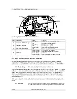
6.6 Dual Channel Indication LEDs
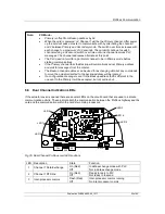
If the actuator cover is opened there are several LEDs on the circuit board that are used to indicate
communication activity. These indicate both the communication between the Profibus highway and the
card and the communication within the card
’s two main processors.
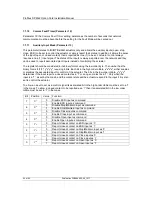
LED Description
State
Function
1
Channel 1 Data Exchange
On (Red)
Off
In data exchange mode with PLC
Not in data exchange mode
2
Channel 1 RTS line
On (Red)
Off
Ready to reply to PLC
Not ready to respond
3
Inter-processor comms
Flash (Red)
Off
Inter-processor comms running
No inter-processor comms
Fig 35: Dual Channel Profibus card LED positions
Note:
FR Mode -
Primary is offset from Backup address by 64.
When the card is powered ‘on’ Channel 1 will be the Primary channel. After power
up the card will seek a master to communicate with by alternating the channel 1
and 2 between Primary and Secondary mode. The switch over time increases with
each change to a maximum of 32 seconds. The card will continue to switch
channels using a 32 second switch over time until one channel receives PLC
messages. The channel addresses alternate at this point.
The PLC need not wait for a particular channel to be in Primary mode before
starting communications.
If the Primary channel fails the Backup will automatically adopt Primary address
and wait for messages from the master.
The Backup channel address can be used for exchanging data but any commands
to move the actuator directed to the backup address will be ignored.
If a configuration message is sent to the Backup address that is different to the
one sent to the Primary it will be accepted, but not carried out.
SK5
SK7
SK10
EPROM
SK1
SK2
SK8
LK1
SK3
LED 3
LED 6
LED 2
LED 4
LED 1
LED 5

