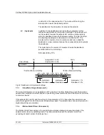
Parameters
Publication PUB088-005-00_1017
65 of 84
P
a
k
s
c
a
n Mo
dbus
Dat
a
Ba
s
e
I
nf
orma
tion
F
ou
nd
ati
on
F
iel
db
us
FF
-01
In
s
tal
lat
io
n m
an
u
al
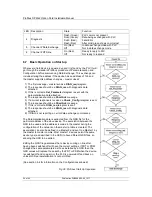
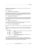
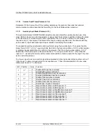
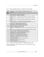
The following examples show how the Auxiliary Input Mask settings can be applied.
Most Significant Bit
Least Significant Bit
Bit 7
Bit 6
Bit 5
Bit 4
Bit 3
Bit 2
Bit 1
Bit 0
X
7
X
6
X
5
X
4
Y
3
Y
2
Y
1
Y
0
Enable
DI-4
ESD
Enable
DI-3
Stop
Enable
DI-2
Close
Enable
DI-1
Open
Invert
DI-4
Invert
DI-3
Invert
DI-2
Invert
DI-1
Example 1
0
0
0
0
1
1
1
1
Example 2
1
1
1
1
1
1
1
1
Example 3
0
0
0
0
0
0
0
0
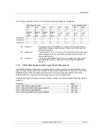
Example 1
The default value of '15' (0000,1111 binary or 0F hex) makes all 4
inputs report closed contacts as true (1) and none of the inputs will
operate the actuator.
Example 2
The value 255 (1111,1111 binary or FF hex) makes all 4 inputs report
closed contacts as true (1) and all the inputs control the actuator in
their predefined way.
Example 3
The value 0 (0000,0000 binary or 00 hex) makes all 4 inputs report
open contacts as true (1) and none of the inputs will operate the
actuator.
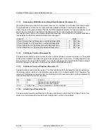
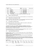
7.1.12
ESD DI-4/Net Disable and Data Logger Disable (Parameter 14)
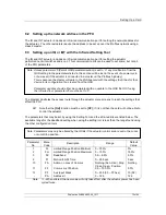
In the IQ/IQT/Skil/EH actuator this input determines the mode of operation for the ESD/DI-4 remote
input. The input can be used either to disable control of the actuator from the network, or to act as an
ESD/digital input. When this setting is made 'Active' the input will disable network control of the
actuator when the contact input is closed irrespective of the Aux Mask setting.
In addition the logging of torque and motor contactor starts count can be inhibited if the data logger is
turned off.
Function
Value
DI-4 = ESD, Data Logger enabled
0
0000 hex
DI-4 = Network disable, Data Logger enabled
1
0001 hex
DI-4 = ESD, Data Logger disabled
2
0010 hex
DI-4 = Network disable, Data Logger disabled
3
0011 hex

