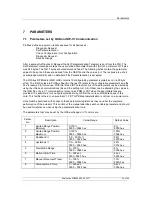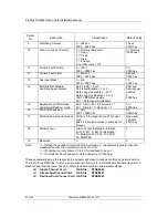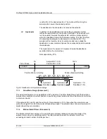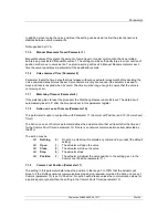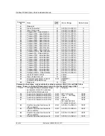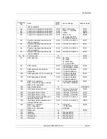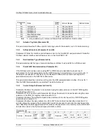
Parameters
Publication PUB088-005-00_1017
73 of 84
P
a
k
s
c
a
n Mo
dbus
Dat
a
Ba
s
e
I
nf
orma
tion
F
ou
nd
ati
on
F
iel
db
us
FF
-01
In
s
tal
lat
io
n m
an
u
al
7.2.12
Function for indication Contacts S1
– S8 (Parameters 78-81 and 86-89)
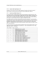
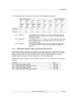
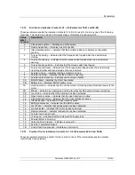
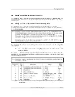
These parameters enable the indication contacts S1 to S8 to be set to trip to any one of the following
functions. The contact can be set to Normally Open or Normally Closed using bit 0.
Value,
Bits 1-
15 (hex)
Description
0
Closed end position
– indicates true limit position.
1
Open end position
– indicates true limit position.
2
Intermediate position
– indicates that the actuator is above or below a configurable
position.
3
Torque trip closing
– indicates that the torque switch tripped when the actuator was
closing.
4
Torque trip opening
– indicates that the torque switch tripped when the actuator was
opening.
5
Torque trip any position
– indicates that the torque switch has tripped.
6
Torque trip mid travel
– indicates that the torque switch tripped when the actuator was
travelling in either direction and was not at an end limit.
7
Actuator closing
– indicates that the actuator is closing.
8
Actuator opening
– indicates that the actuator is opening
9
Actuator output rotating
– indicates centre column rotation.
0A
Motor Stalled
– indicates the motor has stalled.
0B
Battery low
– indicates that the battery is low.
0C
Hand operation
– indicates that the centre column is rotating without electrical power to the
motor.
0D
Blinker
– indicates, by opening and closing the relay that the centre column is rotating.
0E
Local Stop
– indicates that the local stop has been selected.
0F
Open Interlock active
– indicates that the open interlock is active.
10
Close Interlock active
– indicates that the close interlock is active.
11
Interlock active
– open and/or close interlock active.
12
ESD signal present
– indicates that the ESD is active.
13
Lost Phase
– indicates that a phase loss has been detected.
14
Local selected
– indicates that local has been selected.
15
Remote selected
– indicates that remote has been selected.
16
Actuator fault icon present
17
+24V good
– indicates that the customer 24V supply is ok.
18
Actuator Motor is Running
19
Valve fault icon present
– indicates a valve error
1A
Actuator Thermostat tripped
1B
Control fault icon present
– Indicates a control error
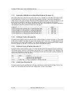
7.2.13
Position Trip for indication Contacts S1
– S8 (Parameters 82-85 and 90-93)
These parameters select the position for the contact to trip at if the Intermediate position contact
function has been selected.

