background image

- 10 -

Ref  No 790 / Art No 980790 

We reserve the right to

make changes without notice

www.rotork.com  www.remotecontrol.se

ROTORK SWEDEN AB

Box 80,  Kontrollvägen 15,  SE-791 22 Falun,  Sweden

Tel: +46 (0)23-587 00  •  Fax: +46 (0)23-587 45  •  falun.info@rotork.com

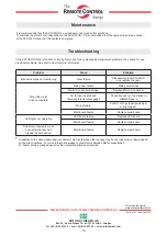
Troubleshooting

If the ACTUATOR fails to function correctly, first check for any mechanical / alignment problems, then check for any

electrical problems. See chart below for more information.

Problem

Cause

Sollution

Manual override not functioning

Gear failure

Disassemble the ACTUATOR

and replace the gear

When the motor

does not operate

Main power failure

Main power check

Motor/ Condenser damage

Replace Motor/ Condenser

Motor over heated and

thermal protector disengaged

Check frequency of operation or

JAMMED gears.

Wiring failure

Confirm unit is properly wired per

wiring diagram

Main board failure

Replace main board

LED lights not operating

LED board failure

Replace LED board

Main board failure

Replace main board

Actuator continues to move

even after the cam has

tripped the limit switch.

Main board failure

Replace main board

In addition to the above described mechanical / electric failures, other causes may be the reason for a failure based 

    on the site conditions. For more information please contact Rotork Sweden AB for consultation.

    For faster service, please have all of the nameplate information avalibe.

Maintenance

It is recommended that the ACTUATOR be cycled every two weeks after purchase.

To minimize the effects of condensation in the ACTUATOR, it is recommended that the cable entries to be sealed

at the ACTUATOR and that the heater is energized.

Summary of Contents for RCEL SA

Page 1: ...scale 0 5 Output Signal 4 20mA DC Load Resistance 750 Wiring Terminals YW 396 2P 3EA 3P 5P connector Visual Indicators 4 LEDS Power Blue Fault Yellow Open Red Close Green Calibration Method ASCN Auto...

Page 2: ...Specification PCU Board A PCU Board B AC INPUT SIGNAL SELECTION AUTOSCAN SPAN ZERO TIME DELAY DEAD BAND 4 20mA DC OUTPUT SIGNAL 4 20mA DC INPUT SIGNAL OUTPUT SIGNAL CONNECTION OPEN AUTO CLOSE AC POWER...

Page 3: ...CU Board A PCU Board B DC INPUT SIGNAL SELECTION AUTOSCAN SPAN ZERO TIME DELAY DEAD BAND 4 20mA DC OUTPUT SIGNAL 4 20mA DC INPUT SIGNAL OUTPUT SIGNAL CONNECTION CCW CW OLS CLS OPEN CLOSE AUTO POWER PO...

Page 4: ...button SPAN Open manual control button Input module button ASCN AUTO SCAN BUTTON ACTUATOR automatic control button delivered from the factory the resistance value of potentiometer may can be changed i...

Page 5: ...mine the value The factory is set to 80 120 If you have not been set 80 120 please reset Refer to page 6 3 POTENTIOMETER CHECK Using the manual lever or handle to the FULL OPEN ACTUATOR then in the sa...

Page 6: ...irection to actuate the open switches AOLS OLS ACLS CLS POTENTIOMETER Setting Actuator delivered full close at 80 120 After limit setting it should check at closed 80 120 Make actuator full closed and...

Page 7: ...plug provided with the ACTUATOR Do not remove the remaining plug as it is already sealed Main Power must only be applied when the top cover is re installed on the actuator body If the main power is on...

Page 8: ...mA 0 10V or 0 5V and 6 18mA 1 9V If you want to change a current signal 1 Optional Modulation DIP SWITCH No 4 Button ON 2 6mA input Push the ZERO BUTTON ACTUATOR CLOSE 4 After the 18mA input SPAN BUTT...

Page 9: ...Limit Power input Wage terminal No 2 No 5 Jump ACTUATOR automatic close open AUTO Button push 25sec Check the resistent value of PIU The resistant value when closed 80 120 4mA Close 20mA Open 4 20mA...

Page 10: ...isengaged Check frequency of operation or JAMMED gears Wiring failure Confirm unit is properly wired per wiring diagram Main board failure Replace main board LED lights not operating LED board failure...

Reviews: