- 2 -
E4L
E4
H
L
H
L
RC210
90
68
120
68
RC220-RC265
90
110
120
110
RC270-RC280,
RC88
100
160
130
160
RCG90-RCG100 155*
200*
185*
200*
Tabell 14pt bold
Bold på rubriker uppe, allt under ska vara regular.
Allt utom spalten med RC-förteckningar ska vara
centrerat i våg och lodrätt. RC-spalten ska vara
vänsterlagd.
Strl på texten varierar beroende på utrymme men
10pt är standard
www.rotork.com www.remotecontrol.se
Installation
Pressure control
The Remote Control Twin Power Actuator is designed for
a normal working pressure of 7 bar (100 psi), but it can be
satisfactorily operated between 4-8 bar (60-140 psi). The
supply air shall be dust and oil free. The air dew point shall
be -20 °C or 10 °C below the ambient temperature. The
maximum particle size must not exceed 40 μm.
The Twin Power actuator specified torque is direct
depending on the air supply pressure. In order to pro
-
duce a constant power output from the motor, an even
air pressure is required. The starting torque of the Twin
Power is approx. 50 % higher than the tightening torque.
If the tightening of the valve takes place at an air pressure
of 6 bar and the air pressure at opening is 5 bar, gives a
decreasing of the starting torque at a given relation to the
decreasing air pressure. If the air supply pressure fluctu
-
ates, a constant pressure regulator should be fitted in the
system. The regulator should be set so it gives a pressure
output equivalent to the lowest incoming pressure.
Oil mist lubrication
To increase the reliability of the Twin Power actuator, an oil
mist lubricator should be fitted as close as possible to the
actuator. For lubrication of the diaphragm motor, control
valve, and the moving parts of the operating cylinder,
an oil mist unit should be fitted not more than one meter
under the Twin Power actuator. At pneumatic operation
where the distance between the actuator and control panel
sideways and at falling pipe exceeding 10 meters, an oil
mist lubricator shall be fitted on the air supply pipe for
clockwise operation. The oil mist lubricator should be filled
with low viscosity oil. The guideline value for adjustment
of the oil mist lubricator is 1-2 drops/minute. Before the air
pipes connects to the actuator they should be cleaned by
air, so that no particles will cause operational disturbance.
To entirely avoid this risk an air cleaner can be fitted.
By new installations all of the air supply pipes shall
carefully be cleaned by air before connection to the
actuator and accessories.
WARNING!
Indicator bridge
Risk for injuries caused by crushing/squeezing and
electrical shocks when the actuator is energized by air
pressure and electricity with its cover off. Before open
-
ing, check that the compressed air and possible power
supply are disconnected. The cover should be mounted
when the actuator operates.
WARNING!
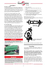
1.
Remove the cover.
2. Disconnect the top part of the terminal block, see
figure 1.
3.
Pull the cable through the cable gland and connect
according to desired wiring diagram.
4. Reconnect the terminal block. Make sure no cables
are close to any moving parts in the actuator.
5.
Put the cover back and tighten the screws.
6. Connect the actuator pneumatically and electrically.
7.
Verify the function of the actuator.
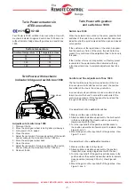
Figure 1
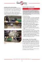
Before testing of the actuator:
Remove the two plastic caps that covers the breathing and
exhaust hole on the air motor.
Air connections for clockwise and anti-clockwise rotation
Operating
Check that the connection for incoming air supplies is cor
-
rect when the actuator operates with auxiliary valves, e.g.
solenoid valves.
When choosing auxiliary valve, i.e. pneumatic 3-way
valves, solenoid valves or hand operated valves, shall
these always be vented after completed operation.
When changing operation direction, the air pipe be-
tween the auxiliary valve and operating unit must be
vented before a new operation starts.
When manually operating with 3-way solenoid valves,
these shall be operated with 3-position switches with neu-
tral centricity. If other equipment is used, the same func
-
tion shall be obtained. At momentary impulse changes, i.e.
when the rotation direction must be changed rapidly, it is
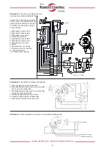
recommended to use the connection according to alterna
-
tive on page 3.
Plastpluggar
borttages
Remove the
plastic caps
Connection for clockwise rotation
Connection for anti-clockwise
rotation


