background image

- 3 -

www.rotork.com  www.remotecontrol.se

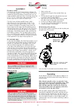
Alternative 1. 

Connection example with sole

-

noid valve and standard indicator bridge

1. Filter, regulator and oil mist lubricator

2. Manually operated pneumatic 3-way valve with    

    spring return for closing NC

3. Manually operated pneumatic 3-way valve with

    spring return for opening NC

4. Pneumatic signal lamp for open valve

5. Pneumatic signal lamp for closed valve

6. Mechanical operated 3-way valve (2x)

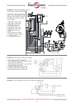
Terminal No. 5 has breaking function 

at open valve. The solenoid valve for 

opening position shall be connected 

to terminal 5 for travel limit function 

in open position.

1. Microswitch, travel control

2. Microswitch, closed valve

3. Microswitch, open valve

4. Connection terminal

5. Signal lamp, closed valve

6. Signal lamp, travel control

7. Signal lamp, open valve

8. Switch

9. Solenoid valve, for closing

10. Solenoid valve, for opening

11. Oil mist lubricator

12. Potentiometer, optional

7

6

5

s

CW

CCW

12

1

3

4

11

10

9

2

8

10

12
11

9
8
7
6
5
4
3
2
1

Option

Ref. No. 015228

Itemref
Designed by

Sheet

Scale

Date

Control

Title/Name, designation, material, dimension etc

Quantity

Item no, comment

1

2

3

4

A

B

C

D

E

F

A

B

C

D

E

F

1

4

2

3

This document is copyright legislationed protected and must not

, without permission from Rotork Sweden AB, be given or handed 

over to any outsider. Trespass give rise to responsibility.

E

Draw. no.

Drawn

Weight [g]

Replace

Rev date

Art. no.

Smoothness where

not spec.

Measures not

tolerance spec.

Elschema indikeringsbrygga TP

015228 B

-


2014-06-05

2015-01-28


Mbi


Size A4


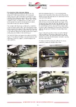
Alternative 3. 

Piston operated 3-way valve for increased operating speed

Air supply

Impulse for closing
Impulse for opening

Alternative 2. 

Pneumatic operating and indicating

Summary of Contents for Remote Control Twin Power

Page 1: ...m turns 175 3 5 18 100 18 32 050 32 65 175S 65 155 100S 155 275 050S 275 550 In cases where the Twin Power actuator will be assem bled on valves with rising stem and rising hand wheel the length of th...

Page 2: ...articles will cause operational disturbance To entirely avoid this risk an air cleaner can be fitted By new installations all of the air supply pipes shall carefully be cleaned by air before connectio...

Page 3: ...nal lamp travel control 7 Signal lamp open valve 8 Switch 9 Solenoid valve for closing 10 Solenoid valve for opening 11 Oil mist lubricator 12 Potentiometer optional 7 6 5 s CW CCW 12 1 3 4 11 10 9 2...

Page 4: ...ded to operate the actuator a few times The function of the Indicator Bridge The indicator bridge has several functions First the latches 3 S1 26 accomplish the by 50 increased starting torque in both...

Page 5: ...s No 1 2 closed to the slide block 3 S1 9 10 so that it can move freely within the whole range Figure 6 shows the adjustment of the stops Damage could occur if the slide block runs against the stops 1...

Page 6: ...sed by crushing squeezing and electrical shocks when the actuator is energized by air pressure and electricity with its cover off WARNING The actuator is provided with two lubrication nipples for a gr...

Page 7: ...on transmitter and visual indication shall be synchronised with the open and closed valve position If the customer at the registration of the order has speci fied the number of turns of the valve this...

Page 8: ...dication is used the hand should now be pointing at open position i e 100 11 Rotate the gear anti clockwise back to the exact closed posi tion and check the number of turns of the valve 12 Make sure t...

Reviews: