- 4 -
E4L
E4
H
L
H
L
RC210
90
68
120
68
RC220-RC265
90
110
120
110
RC270-RC280,
RC88
100
160
130
160
RCG90-RCG100 155*
200*
185*
200*
Tabell 14pt bold
Bold på rubriker uppe, allt under ska vara regular.
Allt utom spalten med RC-förteckningar ska vara
centrerat i våg och lodrätt. RC-spalten ska vara
vänsterlagd.
Strl på texten varierar beroende på utrymme men
10pt är standard
www.rotork.com www.remotecontrol.se
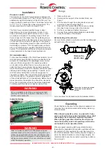
Both the adjustable stops No. 1 and 2 are fastened by
screws in such a position of the slide rod, that they will be
affected by the slide block about 3 mm before this one has
reached its final position.
When the valve now is driven from the end positions the
latch will return into the neutral position by support of the
centering springs. When the latch has released the catch,
the operating cylinder (5:S1) will complete its stroke, and
the normal torque will be connected. The increased start
-
ing torque will be obtained by the fact that the motor shaft
(6:S1/5) changes point of attack on the operating levers
(2:S1/5).
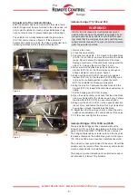
Figure 4 shows the position of the levers at the ”Starting”
Torque and figure 5 shows the position at the normal or
a ”Running” Torque. The increased starting torque will be
obtained only during the initial spindle revolutions counting
from each end position.
To make sure that the setting are sufficient it is recom
-
mended to operate the actuator a few times.
The function of the Indicator Bridge
The indicator bridge has several functions. First, the
latches (3:S1/26) accomplish the by 50 % increased
starting torque in both end positions. Secondly, the micro
switches of the bridge give signals which, when coupled
up to signal lamps, indicate ”open”, ”closed” and ”running”
condition. Further, it is possible to fit, as options, pneu
-
matic switches for open and closed position as well as
pneumatic or electric continuous indication.
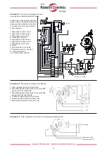
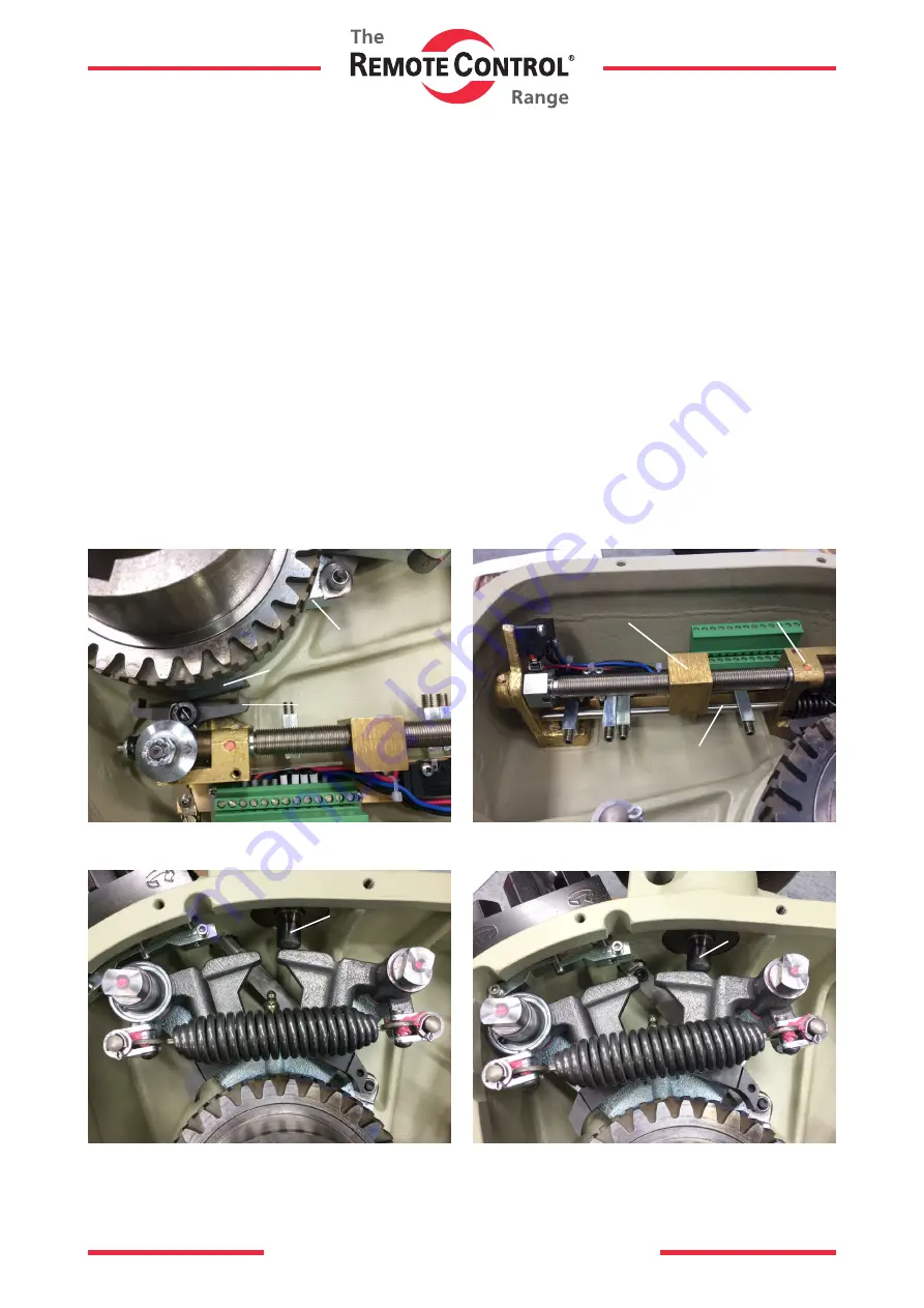
The increased starting torque is obtained by a restriction
of the console movement (2:S1) when changing the rotary
direction, figure 2. By support of the catch (2:S1/12) in the
console this is kept in such a position of the latch (3:S1/26)
on the indicator bridge, that the effect will be the increased
starting torque in relation to the normal torque.
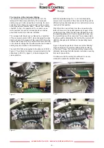
The latch (3:S1/26) is connected to the slide rod (3:S1/41),
figure 3. This slide rod is sliding in an axial direction by the
slide-block (3:S1/9-10), figure 3, in the last stage of the
valve operation.
2:S1
3:S1/26
2:S1/12
Figure 2
Figure 4
6:S1/5
2:S1/5
2:S1/5
Figure 5
2:S1/5
2:S1/5
6:S1/5
Figure 3
3:S1/9-10
3:S1/14
3:S1/41
4
3
2
1


