- 7 -
www.rotork.com www.remotecontrol.se
Twin Power actuators in
ATEX executions
0575 II 2 GD
Twin Power is ATEX certified in two executions. One with
mechanic indicator bridge and switch box 1990 and one
without indicator bridge but with gearbox and switch box
1990.
Surface temperature
Ambient temperature
°
C
Temperature class
70
T6
90
T5
125
T4
150
T3
A
B
C
D
E
F
A
B
C
D
E
F
2
1
3
4
5
6
7
8
1
3
2
7
6
8
4
5
Th
is
d
oc
um
en
t i
s c
op
yr
ig
ht
le
gi
sla
tio
ne
d
pr
ot
ec
te
d
a
nd
m
us
t n
ot
, w
ith
ou
t p
er
m
iss
io
n
fro
m
R
em
ot
e
C
on
tro
l A
B,
b
e
gi
ve
n
or
h
an
d
ed
o
ve
r t
o
a
ny
o
ut
sid
er
. T
re
sp
a
ss
g
iv
e
ris
e
to
re
sp
on
sib
ilit
y.
Measures not
tolerance spec.
Smoothness where
Title/Name, designation, material, dimension etc
Drawn
Itemref
Designed by
Quantity
Control
not spec.
E
Replace
Weight [g]
Rev date
Draw. no.
Sheet
Comment
Date
Scale
Art. no.
TP 114 m brygga för 1990
004610
2004-04-23
A.0
-
2004-04-23
stn
Size A3
Print date 2004-06-03
Gear wheel
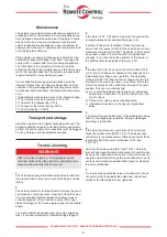
Adjustment of switch box 1990
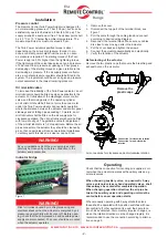
1. Dismount the lid.
2. Move the small gear wheel (see Fig above) sideways.
3. Follow point 2 to 9, page 5.
4. Close the valve.
5. Adjust the limit switch (for closed position) of the switch
box according to the instruction for the 1990 box.
6. Move the small gear wheel back.
7. Open the valve.
8. Adjust the limit switch (for open position) of the switch
box according to the instruction for the 1990 box.
9. Remount the lid.
Twin Power with mechanic
indicator bridge and switch box 1990
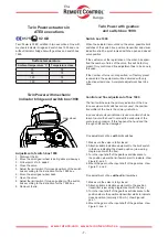
Twin Power with gearbox
and switch box 1990
Switch box 1990
When the actuator is mounted on the valve, possible limit
switches of the switch box, position transmitter and visual
indication shall be synchronised with the open and closed
valve position.
If the customer, at the registration of the order, has speci
-
fied the number of turns of the valve, this will be factory
preset. Only control and fine adjustment has to be done in
this case.
If the number of turns is not specified, or if factory preset
is unwanted, the equipment will be delivered with only
a functional test done. A complete adjustment has to be
done.
Control and fine adjustment of box 1990
The limit switches are the primary indication of the box.
In cases where limit switches are not used, the position
transmitter of the box is the primary indication.
In cases where visual indication is used, caution shall be
taken to avoid the hand to exceed the endpoints of the
scale in any occasion. If this happens the hand and the
through shaft can be damaged.
Fine adjustment of box
with
limit switches:
1. Make sure the valve is fully closed.
2. Attach suitable indication equipment to the limit switch
in the box indicating the closed position (view wiring
diagram sent with the box).
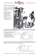
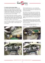
3. Turn the input shaft of the gearbox anticlockwise to
the position where the limit switch start to indicate. View
Figure B, pos. 1.
4. Mount the gear on the input shaft of the gearbox. View
Figure C, pos. 2.
Fine adjustment of box
without
limit switches:
1. Make sure the valve is fully closed.
2. Attach suitable indication equipment to the position
transmitter (view wiring diagram sent with the box).
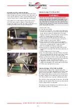
3. Turn the input shaft of the gearbox anticlockwise to the
position where the position transmitter starts to indicate
closed position (normally 4.00 mA). View Figure B
pos. 1.
4. Mount the gear on the input shaft of the gearbox. View
Figure C pos. 2.


