10
Commissioning
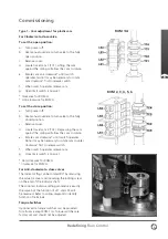
Type 2 - Cam adjustment for ROM 1/A
The following instruction is only applicable to
situation that the valve is clockwise for closing
(from the top view).
a. Turn power off.
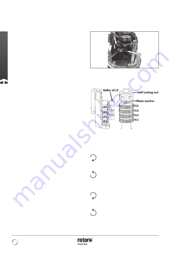
b. Remove cover and unscrew the self-locking nut
anticlockwise twice approximately 60 degree
each time from position A to B as shown in
picture D by inserting 4.0mm Allen key into the
hole of self-locking nut.
Note: the Allen key should be flat head and
longer than 100mm.
c. Set fully open position by following item
1, 2, 3 below.
1. Use manual override to turn valve to the
fully open position.
2. Make sure the roller of LS1 is touching
the cylindrical surface of TC1.
3.
Case 1:
For ROM 1, rotate TC1 anti-clockwise
slowly until a light click is heard.
Case 2:
For ROM A, rotate TC1 clockwise
slowly until a light click is heard.
d. Set fully closed position by following item
1, 2, 3 below:
1. Use manual override to turn valve to the
fully closed position.
2. Make sure the roller of LS2 is touching the
cylindrical surface of TC2.
3.
Case 1:
For ROM 1, rotate TC2 clockwise
slowly until a light click is heard.
Case 2:
For ROM A, rotate TC2
anti-clockwise slowly until a light click
is heard.
e. Screw the self-locking nut clockwise to original
position (approximately twice 60 degree ).
f. Apply power to check the travelling position, if
the position is not correct, please repeat steps
a - f.
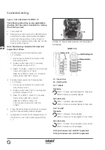
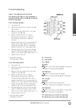
TC: Travel Cam
LS: Limit Switch
TC1: “OPEN”
Clockwise
ROM 1: Increase opening degree to fully open
ROM A: Decrease opening degree
Anti-clockwise
ROM 1: Decrease opening degree
ROM A: Increase opening degree to fully open
TC2: “CLOSE”
Clockwise
ROM 1: Decrease closing degree
ROM A: Increase closing degree to fully closed
Anti-clockwise
ROM 1: Increase closing degree to fully closed
ROM A: Decrease closing degree
TC3: Synchronous turn with TC1 (optional)
TC4: Synchronous turn with TC2 (optional)
ROM 1/A
Picture D: Travel from position A to B is about
60 degree
A
B


