9
Redefining Flow Control
Commissioning
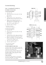
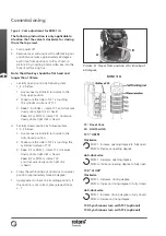
Type 1 - Cam adjustment for plastic cam
For Clockwise to close valve
To set the open position:
a. Turn power off.
b. Use manual override to turn valve to the fully
open position.
c. Remove cover.
d. Locate travel cam 1 (TC1). Lifting the cam
against the spring will allow the cam to rotate.
e. Rotate cam anti-clockwise* until switch
operates. Note: it may be necessary to rotate
cam clockwise
+
first to release switch.
f. When switch operates release cam.
g. Open limit switch is now set.
* Clockwise for ROM A
+
Anti-clockwise for ROM A
To set the close position:
a. Turn power off.
b. Use manual override to turn valve to the fully
closed position.
c. Remove cover.
d. Locate travel cam 2 (TC2). Depressing the cam
against the spring will allow the cam to rotate.
e. Rotate cam clockwise* until switch operates.
Note: it may be necessary to rotate cam counter
clockwise
+
first to release switch.
f. When switch operates release cam.
g. Close limit switch is now set.
* Anti-clockwise for ROM A
+
Clockwise for ROM A
For Anti-clockwise to close valves
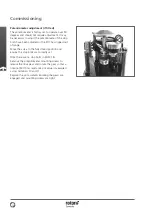
The indicator flag can be rotated 90º by removing
the actuator cover and loosening the locking screw
on the end of the indicator shaft.
The counter clockwise setting procedure is exactly
the same but the function of LS1 and LS2 will
be reversed. Refer to wiring diagram to identify
function of terminals.
Torque Switches
Optional extra torque switches can be provided
for all sizes except ROM 1/A. Torque switches are
factory set and should not be adjusted.
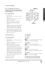
ROM 1/A
ROM 2, 3, 4, 5, 6


