background image

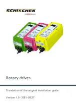
Rotary drives

Translation of the original installation guide

Version 1.0 · 2021-05-27

Summary of Contents for Schischek InMax

Page 1: ...Rotary drives Translation of the original installation guide Version 1 0 2021 05 27 ...

Page 2: ...chek GmbH Mühlsteig 45 Gewerbegebiet Süd 5 90579 Langenzenn Germany Tel 49 9101 9081 0 Fax 49 9101 9081 77 Email info de schischek com 2 Translation of the original installation guide Version 1 0 2021 05 27 ...

Page 3: ... as a function of supply voltage 57 3 9 Wire cross sections for the supply 58 3 10 Technical data 59 3 10 1 Note on nominal values 59 3 10 2 Max 5 10 Max 5 10 CTS Max 5 10 VAS 60 3 10 3 Max 5 10 Y Max 5 10 Y CTS Max 5 10 Y VAS 62 3 10 4 Max 5 10 S Max 5 10 S CTS Max 5 10 S VAS 65 3 10 5 Max 5 10 F Max 5 10 F CTS Max 5 10 F VAS 67 3 10 6 Max 5 10 SF Max 5 10 SF CTS Max 5 10 SF VAS 69 3 10 7 Max 5 1...

Page 4: ...30 CY 117 3 10 26 Max 8 F1 Max 8 F1 CTS Max 8 F1 VAS 119 3 10 27 Max 8 SF1 Max 8 SF1 CTS Max 8 SF1 VAS 121 3 10 28 Max 8 BF1 Max 8 BF1 CTS Max 8 BF1 VAS 124 3 10 29 Max 30 BF Max 30 BF CTM 126 3 10 30 Max 30 BF3 Max 30 BF3 CTM 129 3 10 31 Max 30 F Max 30 F CTM 131 3 10 32 Max 30 F3 Max 30 F3 CTM Max 30 F3 VAM 133 3 10 33 Max 30 SF Max 30 SF CTM Max 30 SF VAM 135 3 10 34 Max 30 SF3 Max 30 SF3 CTM M...

Page 5: ...ortation 189 4 2 Packaging 189 4 3 Storage 189 5 Installation and commissioning 190 5 1 Axle connection 195 5 2 Preparing for installation 195 5 3 Installation on air dampers interlocking axle connection 197 5 3 1 Parameter setting 198 5 4 Installation on air dampers friction locked axle connection 201 5 5 Installation on fire dampers 202 5 6 Installation on ball cocks and throttle valves 203 5 7 ...

Page 6: ...6 1 7 Synchronous operation 212 6 1 8 Mechanical protection only F1 F3 types 212 6 1 9 Power outage 212 7 Maintenance 213 8 Troubleshooting 215 9 Uninstalling decommissioning disposal 220 10 EU declaration of incorporation as set out in the EC Machinery Directive 2006 42 EC Annex II B 222 11 EU Declaration of Conformity 224 12 EU Declaration of Conformity 226 13 EU Declaration of Conformity 228 6 ...

Page 7: ...nstallation guide because insufficient aware ness of the contents can have profound consequences Insufficient knowledge or a failure to observe the installation guide can result in serious in jury irreparable damage to property or impaired performance for the rotary drive No liability is accepted for damage caused by insufficient knowledge of the installation guide The original version of this ins...

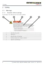
Page 8: ...his document are structured as follows 1 2 3 4 5 1 Hazard specific symbol 2 Signal word 3 Type and source of the danger 4 Possible consequences of failure to observe 5 Approach to avoid danger 2 Safety 8 Translation of the original installation guide Version 1 0 2021 05 27 ...

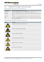
Page 9: ...ates a potentially dangerous situation which could result in minor injury NOTE Indicates a potentially dangerous situation which could result in damage to prop erty or the environment The following hazard symbols are used in this document Symbol Meaning General warning about a hazardous area Warning dangerous electrical voltage Warning explosive substances Warning obstacles at ground level Warning...

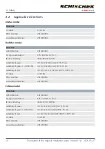
Page 10: ... dust II 3 3 D Ex tc ic Dc IIIC T80 C T95 C Dc CE label CE 0158 EMC directive 2014 30 EU Low voltage directive 2014 35 EU ExMax model Directive ATEX directive 2014 34 EU EU type examination EPS 17 ATEX 1 132 X IECEx conformity IECEx EPS 17 0065X Labelling of gases II 2 2 G Ex db ib Gb IIC T6 T5 Gb Labelling of gases CTS CTM II 2 2 G Ex db ib Gb IIB T6 T5 Gb Labelling of dust II 2 2 D Ex tb ib Db I...

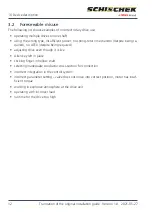
Page 11: ...ndustrial ap plications with explosion protection gas mist steam dust for installation in areas with ex plosion protection Zones 1 2 21 and 22 Any other use is not intended and thus not permitted Non compliance will invalidate the warranty and any warranty claims Different torque ranges models and equipment options enable different application areas blind dampers control dampers and shut off valve...

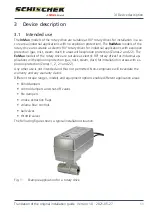
Page 12: ... it is live Allen key left in place sticking finger in hollow shaft selecting inadequate conductor cross section for connection incorrect integration in the control system incorrect parameter setting valve does not move into correct position motor has insuf ficient torque working in explosive atmosphere at the drive unit operating with incorrect load runtime for the drive too high 3 Device descrip...

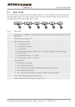
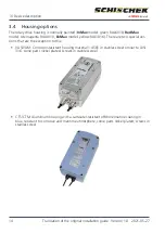
Page 13: ...ons Y continuous version S integrated limit switch F spring return BF fire prevention design spring return can also be triggered via the temperature sensor Pro TT F1 spring return within 1 s size S F3 spring return within 3 s size M 4 Housing options Not specified aluminium VAS stainless steel size S CTS aluminium housing with salt water resistant paintwork size S VAM stainless steel size M CTM al...

Page 14: ...AS VAM Corrosion resistant housing material 1 4581 in stainless steel similar to AISI 316 some parts nickel plated screws in stainless steel CTS CTM Aluminium housing with a saltwater resistant offshore marine coating in blue resistant to corrosive and maritime atmosphere some parts nickel plated screws in stainless steel 3 Device description 14 Translation of the original installation guide Versi...

Page 15: ...maximum load 500 g S9 No thermal cutoff only available as InMax Limit switch configured to 0 80 instead of 5 85 S12 Drive unit without anti backdrive mechanism drive can be turned back by external load when the power is switched off S14 To 60 C Restrictions for ExMax and RedMax Temperature class T4 only suitable for 110 V 240 V cannot be supplied for Y drives S17 Cable length 3 0 m S18 Drive unit ...

Page 16: ...nts maximum load 500 g Cable length 3 0 m To 60 C Restrictions for ExMax and RedMax Temperature class T4 only suitable for 110 V 240 V maximum 25 duty cycle cannot be supplied for Y drives S33 Cable length 3 0 m To 60 C Restrictions for ExMax and RedMax Temperature class T4 only suitable for 110 V 240 V maximum 25 duty cycle cannot be supplied for Y drives S36 Drive unit without anti backdrive mec...

Page 17: ...ed locally The modular design enables upgrades with adjustable auxiliary switches and other accessor ies All rotary drives are distinguished by the following performance characteristics 100 blocking resistance Drives made from stainless steel and sintered steel Integrated heating to 40 C ambient temperature Integrated safety temperature limiter Concealed controls for parameter setting button LED s...

Page 18: ...s current 10 A must be provided at the installation location The start up current is approx 2 A for approx 1 second Depending on the version integrated limit switches signal the rotation angle setting In this section the nominal values of the cable diameters are specified without the tolerances required in production 3 7 1 Cable types and circuit diagrams for size S 3 7 1 1 Versions XX S 3 7 1 1 1...

Page 19: ...nction of switches a and b see 3 point standard operation p 211 3 7 1 1 3 1 wire with spring return constant spring return period For 1 wire control the heating is not active if contact is broken Caution 24 240 VAC DC PE 1 2 3 4 PA Fig 5 SB2 3 cable type 4 PE cable diameter 7 2 mm 3 Device description Translation of the original installation guide Version 1 0 2021 05 27 19 ...

Page 20: ... 3 4 5 6 5 85 U 90 V AC DC U 90 V AC DC 2 A 10 A slow 5 A 10 A slow min max Fig 6 SB3 0 cable type 5 PE cable diameter 7 5 mm cable type 6 cable diameter 7 4 mm 3 7 1 2 Versions XX Y 3 7 1 2 1 3 point no spring return 24 240 VAC DC PE a b 1 2 3 4 PA Fig 7 SB1 0 cable type 4 PE cable diameter 7 2 mm For explanation of the function of switches a and b see 3 point standard operation p 211 3 Device de...

Page 21: ...nction of switches a and b see 3 point standard operation p 211 3 7 1 2 3 1 wire with spring return constant spring return period For 1 wire control the heating is not active if contact is broken Caution 24 240 VAC DC PE 1 2 3 4 PA Fig 9 SB2 3 cable type 4 PE cable diameter 7 2 mm 3 Device description Translation of the original installation guide Version 1 0 2021 05 27 21 ...

Page 22: ...ressing the button T for at least 3 s Fig 10 SB5 1 cable type 5 PE cable diameter 7 5 mm cable type 6 cable diameter 7 4 mm 3 7 1 2 5 1 wire with spring return with constant spring return period continuous Self adaptation 24 240 VAC DC PE 1 2 3 4 PA 1 2 3 4 5 6 YmA YVDC T VDC mA UmA UVDC Bridge 3 4 inverts the input and feedback signals Inverse operation Automatic alignment of positioning signal a...

Page 23: ... feedback signal Self adaptation 24 240 VAC DC PE 1 2 3 4 PA a b 1 2 3 4 5 6 T VDC mA UmA UVDC 3 pt activation Bridge 3 4 inverts the feedback signals Inverse operation 5 Spring return in 10 s default connection Spring return in 3 s additional bridge to terminal 5 Runtime option for spring return drives Caution When converting from continuous to 3 point mode note function b closed a open CLOSED OP...

Page 24: ...peration 5 Spring return in 10 s default connection Spring return in 3 s additional bridge to terminal 5 Runtime option for spring return drives a closed forced OPEN CLOSED depending on left right installation of the drive Automatic alignment of positioning signal and feedback signal with regard to the angle of rotation or travel is done by pressing the button T for at least 3 s Fig 14 SB5 0 cable...

Page 25: ...t installation of the drive b closed forced CLOSED OPEN depending on left right installation of the drive Automatic alignment of positioning signal and feedback signal with regard to the angle of rotation or travel is done by pressing the button T for at least 3 s Fig 15 SB4 0 cable type 5 PE cable diameter 7 5 mm cable type 6 cable diameter 7 4 mm For explanation of the function of switches a and...

Page 26: ...oken Caution Fig 16 SB2 1 cable type 5 PE cable diameter 7 5 mm 3 7 1 3 2 3 point with spring return with configurable spring return period 24 240 VAC DC PE a b 1 2 3 4 PA 5 Spring return in 10 s default connection Spring return in 3 s additional bridge to terminal 5 Fig 17 SB2 0 cable type 5 PE cable diameter 7 5 mm For explanation of the function of switches a and b see 3 point standard operatio...

Page 27: ... s Fig 18 SB6 1 cable type 5 PE cable diameter 7 5 mm 3 7 1 3 4 Without spring return continuous activation Self adaptation 24 240 VAC DC PE 1 2 PA 3 4 5 YmA T GND UVDC Automatic alignment of positioning signal and feedback signal with regard to the angle of rotation or travel is done by pressing the button T for at least 3 s Fig 19 SB6 0 cable type 5 PE cable diameter 7 5 mm 3 Device description ...

Page 28: ...A Fig 20 SB1 0 cable type 4 PE cable diameter 7 2 mm 3 7 1 4 2 3 point with spring return constant spring return period 24 240 VAC DC PE a b 1 2 3 4 PA Fig 21 SB2 2 cable type 4 PE cable diameter 7 2 mm 3 Device description 28 Translation of the original installation guide Version 1 0 2021 05 27 ...

Page 29: ...rsions XX SF 3 7 1 5 1 1 wire with spring return with configurable spring return period 24 240 VAC DC PE 1 2 3 4 PA 5 Spring return in 10 s default connection Spring return in 3 s additional bridge to terminal 5 For 1 wire control the heating is not active if contact is broken Caution Fig 23 SB2 1 cable type 5 PE cable diameter 7 5 mm 3 Device description Translation of the original installation g...

Page 30: ...ressing the button T for at least 3 s Fig 24 SB6 1 cable type 5 PE cable diameter 7 5 mm 3 7 1 5 3 3 point with spring return with configurable spring return period 24 240 VAC DC PE a b 1 2 3 4 PA 5 Spring return in 10 s default connection Spring return in 3 s additional bridge to terminal 5 Fig 25 SB2 0 cable type 5 PE cable diameter 7 5 mm 3 Device description 30 Translation of the original inst...

Page 31: ... 5 5 Integrated limit switch Integrated auxiliary switch fuse on power supply side recommended Connection of drive unit depending on type and application as per circuit diagrams above Connection of integrated potential free auxiliary switch 24 240 VAC DC PE 1 2 3 4 PA a b 1 2 3 4 5 6 5 85 U 90 V AC DC U 90 V AC DC 2 A 10 A slow 5 A 10 A slow min max Fig 27 SB3 0 cable type 5 PE cable diameter 7 5 ...

Page 32: ...uous Self adaptation Inverse operation 24 240 VAC DC PE 1 2 3 4 PA 1 2 3 4 5 6 YmA YVDC T VDC mAUmA UVDC 5 Spring return in 10 s default connection Spring return in 3 s additional bridge to terminal 5 Runtime option for spring return drives Bridge 3 4 inverts the input and feedback signals Automatic alignment of positioning signal and feedback signal with regard to the angle of rotation or travel ...

Page 33: ...mm 3 7 1 6 4 1 wire with spring return continuous without feedback signal Self adaptation 24 240 VAC DC PE 1 2 3 4 PA 1 2 3 4 5 6 YmA YVDC T VDC mA Bridge 3 4 inverts the input signals Inverse operation 5 Spring return in 10 s default connection Spring return in 3 s additional bridge to terminal 5 Runtime option for spring return drives Automatic alignment of positioning signal and feedback signal...

Page 34: ...tion and override control in continuous mode a closed Bridge 3 4 inverts the input and feedback signals Inverse operation forced OPEN CLOSED depending on left right installation of the drive b closed forced CLOSED OPEN depending on left right installation of the drive Automatic alignment of positioning signal and feedback signal with regard to the angle of rotation or travel is done by pressing th...

Page 35: ...eturn in 10 s default connection Spring return in 3 s additional bridge to terminal 5 Fig 34 SB2 0 cable type 5 PE cable diameter 7 5 mm For explanation of the function of switches a and b see 3 point standard operation p 211 3 Device description Translation of the original installation guide Version 1 0 2021 05 27 35 ...

Page 36: ...nection Spring return in 3 s additional bridge to terminal 5 Runtime option for spring return drives a closed forced OPEN CLOSED depending on left right installation of the drive Automatic alignment of positioning signal and feedback signal with regard to the angle of rotation or travel is done by pressing the button T for at least 3 s Fig 35 SB5 0 cable type 5 PE cable diameter 7 5 mm cable type ...

Page 37: ...ontinuous to 3 point mode note function b closed a open CLOSED OPEN depending on left right installation of the drive a closed b open OPEN CLOSED depending on left right installation of the drive Automatic alignment of positioning signal and feedback signal with regard to the angle of rotation or travel is done by pressing the button T for at least 3 s Fig 36 SB5 3 cable type 5 PE cable diameter 7...

Page 38: ...s XX BF 3 7 1 7 1 1 wire with spring return with configurable spring return period BF Integrated auxiliary switch fuse on power supply side recommended 24 240 VAC DC PE 1 2 3 4 PA 5 6 7 8 9 10 5 85 U 90 V AC DC U 90 V AC DC 2 A 10 A slow 5 A 10 A slow min max Caution For 1 wire control the heating is not active if contact is broken 1 2 Ex i trip circuit for ExPro TT Safety temperature trigger ExPr...

Page 39: ...tion p 211 3 7 1 8 Versions XX TR 3 7 1 8 1 1 wire with spring return with configurable spring return period TR The voltage to auxiliary switches must be identical to the supply voltage and be protected with the same fuse if services are switched on Integrated permanently installed auxiliary switches potential free switching at 5 and 85 angle of rotation max 24 V 3 A 250 V 0 25 A min 5 V 5 mA Spri...

Page 40: ... contact is broken Caution 24 240 VAC DC PE 1 2 3 PA Fig 41 SB2 5 cable type 3 PE cable diameter 6 mm 3 7 1 9 2 2 wire with spring return constant spring return period F1 F3 24 240 VAC DC PE a 1 2 3 PA Fig 42 SB2 4 cable type 3 PE cable diameter 6 mm 3 Device description 40 Translation of the original installation guide Version 1 0 2021 05 27 ...

Page 41: ...if contact is broken Caution 24 240 VAC DC PE 1 2 3 PA Fig 43 SB2 5 cable type 3 PE cable diameter 6 mm 3 7 1 10 2 2 wire with spring return constant spring return period F1 24 240 VAC DC PE a 1 2 3 PA Fig 44 SB2 4 cable type 3 PE cable diameter 6 mm 3 Device description Translation of the original installation guide Version 1 0 2021 05 27 41 ...

Page 42: ...le type 5 PE cable diameter 7 5 mm cable type 6 cable diameter 7 4 mm 3 7 1 11 Versions XX BF1 3 7 1 11 1 1 wire with spring return constant spring return period BF1 BF3 Integrated auxiliary switch fuse on power supply side recommended 24 240 VAC DC PE 1 2 3 4 PA 5 6 7 8 9 10 5 85 U 90 V AC DC U 90 V AC DC 2 A 10 A slow 5 A 10 A slow min max 1 2 Ex i trip circuit for ExPro TT Safety temperature tr...

Page 43: ...ution 24 240 VAC DC PE 1 2 3 4 PA Fig 47 SB2 3 cable type 4 PE cable diameter 7 2 mm 3 7 2 1 2 3 point with spring return constant spring return period 24 240 VAC DC PE a b 1 2 3 4 PA Fig 48 SB2 2 cable type 4 PE cable diameter 7 2 mm For explanation of the function of switches a and b see 3 point standard operation p 211 3 Device description Translation of the original installation guide Version ...

Page 44: ...se on power supply side recommended Connection of drive unit depending on type and application as per circuit diagrams above Connection of integrated potential free auxiliary switch 24 240 VAC DC PE 1 2 3 4 PA a b 1 2 3 4 5 6 5 85 U 90 V AC DC U 90 V AC DC 2 A 10 A slow 5 A 10 A slow min max Fig 50 SB3 0 cable type 5 PE cable diameter 7 5 mm cable type 6 cable diameter 7 4 mm 3 Device description ...

Page 45: ...switches a and b see 3 point standard operation p 211 3 7 2 2 2 3 point with spring return constant spring return period 24 240 VAC DC PE a b 1 2 3 4 PA Fig 52 SB2 2 cable type 4 PE cable diameter 7 2 mm For explanation of the function of switches a and b see 3 point standard operation p 211 3 Device description Translation of the original installation guide Version 1 0 2021 05 27 45 ...

Page 46: ...PA 1 2 3 4 5 6 YmA YVDC T VDC mAUmA UVDC 5 Spring return in 10 s default connection Spring return in 3 s additional bridge to terminal 5 Runtime option for spring return drives Bridge 3 4 inverts the input and feedback signals Automatic alignment of positioning signal and feedback signal with regard to the angle of rotation or travel is done by pressing the button T for at least 3 s Fig 54 SB5 1 c...

Page 47: ...mm 3 7 2 2 6 1 wire with spring return continuous without feedback signal Self adaptation 24 240 VAC DC PE 1 2 3 4 PA 1 2 3 4 5 6 YmA YVDC T VDC mA Bridge 3 4 inverts the input signals Inverse operation 5 Spring return in 10 s default connection Spring return in 3 s additional bridge to terminal 5 Runtime option for spring return drives Automatic alignment of positioning signal and feedback signal...

Page 48: ...ontinuous to 3 point mode note function b closed a open CLOSED OPEN depending on left right installation of the drive a closed b open OPEN CLOSED depending on left right installation of the drive Automatic alignment of positioning signal and feedback signal with regard to the angle of rotation or travel is done by pressing the button T for at least 3 s Fig 57 SB5 3 cable type 5 PE cable diameter 7...

Page 49: ...nection Spring return in 3 s additional bridge to terminal 5 Runtime option for spring return drives a closed forced OPEN CLOSED depending on left right installation of the drive Automatic alignment of positioning signal and feedback signal with regard to the angle of rotation or travel is done by pressing the button T for at least 3 s Fig 58 SB5 0 cable type 5 PE cable diameter 7 5 mm cable type ...

Page 50: ...t installation of the drive b closed forced CLOSED OPEN depending on left right installation of the drive Automatic alignment of positioning signal and feedback signal with regard to the angle of rotation or travel is done by pressing the button T for at least 3 s Fig 59 SB4 0 cable type 5 PE cable diameter 7 5 mm cable type 6 cable diameter 7 4 mm For explanation of the function of switches a and...

Page 51: ... 3 4 PA Fig 60 SB2 3 cable type 4 PE cable diameter 7 2 mm 3 7 2 3 2 3 point with spring return constant spring return period 24 240 VAC DC PE a b 1 2 3 4 PA Fig 61 SB2 2 cable type 4 PE cable diameter 7 2 mm For explanation of the function of switches a and b see 3 point standard operation p 211 3 Device description Translation of the original installation guide Version 1 0 2021 05 27 51 ...

Page 52: ...n period BF Integrated auxiliary switch fuse on power supply side recommended 24 240 VAC DC PE 1 2 3 4 PA 5 6 7 8 9 10 5 85 U 90 V AC DC U 90 V AC DC 2 A 10 A slow 5 A 10 A slow min max Caution For 1 wire control the heating is not active if contact is broken 1 2 Ex i trip circuit for ExPro TT Safety temperature trigger ExPro TT C Test button 11 Fig 63 SB7 2 cable type 10 PE cable diameter 9 4 mm ...

Page 53: ...igger ExPro TT C Test button 11 Fig 64 SB7 3 cable type 10 PE cable diameter 9 4 mm For explanation of the function of switches a and b see 3 point standard operation p 211 3 7 2 5 Versions XX F3 3 7 2 5 1 1 wire with spring return constant spring return period F3 For 1 wire control the heating is not active if contact is broken Caution 24 240 VAC DC PE 1 2 3 PA Fig 65 SB2 5 cable type 3 PE cable ...

Page 54: ... 6 mm 3 7 2 6 Versions XX SF3 3 7 2 6 1 1 wire with spring return constant spring return period F3 For 1 wire control the heating is not active if contact is broken Caution 24 240 VAC DC PE 1 2 3 PA Fig 67 SB2 5 cable type 3 PE cable diameter 6 mm 3 Device description 54 Translation of the original installation guide Version 1 0 2021 05 27 ...

Page 55: ...ended Connection of drive unit depending on type and application as per circuit diagrams above Connection of integrated potential free auxiliary switch 24 240 VAC DC PE 1 2 3 4 PA a b 1 2 3 4 5 6 5 85 U 90 V AC DC U 90 V AC DC 2 A 10 A slow 5 A 10 A slow min max Fig 69 SB3 0 cable type 5 PE cable diameter 7 5 mm cable type 6 cable diameter 7 4 mm 3 Device description Translation of the original in...

Page 56: ...ecommended 24 240 VAC DC PE 1 2 3 4 PA 5 6 7 8 9 10 5 85 U 90 V AC DC U 90 V AC DC 2 A 10 A slow 5 A 10 A slow min max 1 2 Ex i trip circuit for ExPro TT Safety temperature trigger ExPro TT C Test button 11 Fig 70 SB7 4 cable type 9 PE cable diameter 8 8mm 3 Device description 56 Translation of the original installation guide Version 1 0 2021 05 27 ...

Page 57: ...40 V AC 0 13 A 0 09 A 0 07 A 0 06 A 0 06 A The holding power irrespective of the run period is typically 5 W The heat output is 16 W In heating mode the motor is not running When the supply voltage is switched on the switching power supply for the drive needs 2 0 A to start up The switch on pulse lasts approx 1 second This must be taken into ac count when sizing the wire cross section Depending on...

Page 58: ...re cross section for the power supply The following formulae allow you to calculate the necessary cross section of the wire or the maximum wire length for the cross section being used Alternatively a transformer can be used to increase the secondary voltage A 0 0714 L UV 18 V A wire cross section mm2 L wire length m UV supply voltage V Factor 0 0714 drive specific factor Vmm2 m L A UV 21 6 V 0 071...

Page 59: ...stead just a nominal value nom There are too many interdependent in fluences on the tolerance range to give generally applicable technically meaningful values Please get in touch if you need detailed information on this Contact details can be found on page 2 3 Device description Translation of the original installation guide Version 1 0 2021 05 27 59 ...

Page 60: ...H 1 1 1 210 96 80 1 1 1 mm mm mm Max 5 10 CTS L W H 1 1 1 210 96 80 1 1 1 mm mm mm Max 5 10 VAS L W H 1 1 1 211 96 81 1 1 1 mm mm mm Hollow shaft double square 12 12 mm Allen key provided for manual adjustment in accordance with these instructions 3 mm Electrical characteristics min typ max unit Minimum nominal voltage at room temperature 10 24 10 VAC DC Maximum nominal voltage at room temperature...

Page 61: ...n 100 Electrical connection options Cable type 4 PE cable diameter 7 2 mm 3 point no spring return p 18 3 point with spring return constant spring return period p 19 1 wire with spring return constant spring return period p 19 Environmental conditions min typ max unit Humidity not condensing 90 rH Protection class as per DIN EN 60529 IP66 Operation Ambient temperature T6 Ambient temperature T5 40 ...

Page 62: ...Y L W H 1 1 1 210 96 80 1 1 1 mm mm mm Max 5 10 Y CTS L W H 1 1 1 210 96 80 1 1 1 mm mm mm Max 5 10 Y VAS L W H 1 1 1 211 96 81 1 1 1 mm mm mm Hollow shaft double square 12 12 mm Allen key provided for manual adjustment in accordance with these instructions 3 mm Electrical characteristics min typ max unit Minimum nominal voltage at room temperature 10 24 10 VAC DC Maximum nominal voltage at room t...

Page 63: ...pring return period p 19 1 wire with spring return constant spring return period p 19 Cable type 6 cable diameter 7 4 mm 1 wire with spring return with con figurable spring return period con tinuous p 22 1 wire with spring return with con stant spring return period continuous p 22 1 wire with spring return continu ous without feedback signal p 23 3 point with spring return with con figurable sprin...

Page 64: ...VDC mA Inverting Setting up wire bridges between ter minals 3 and 4 Environmental conditions min typ max unit Humidity not condensing 90 rH Protection class as per DIN EN 60529 IP66 Operation Ambient temperature T6 Ambient temperature T5 40 40 40 50 C C Storage Ambient temperature 40 70 C Nominal value please note that nominal values are also subject to tolerances For more detailed information see...

Page 65: ... L W H 1 1 1 210 96 80 1 1 1 mm mm mm Max 5 10 S CTS L W H 1 1 1 210 96 80 1 1 1 mm mm mm Max 5 10 S VAS L W H 1 1 1 211 96 81 1 1 1 mm mm mm Hollow shaft double square 12 12 mm Allen key provided for manual adjustment in accordance with these instructions 3 mm Electrical characteristics min typ max unit Minimum nominal voltage at room temperature 10 24 10 VAC DC Maximum nominal voltage at room te...

Page 66: ...forced pause after 3 s motor operation 100 Electrical connection options Cable type 4 PE cable diameter 7 2 mm 3 point no spring return p 18 3 point with spring return constant spring return period p 19 1 wire with spring return constant spring return period p 19 Cable type 6 cable diameter 7 4 mm Integrated limit switch p 20 Electrical characteristics limit switch min typ max unit Switch point CL...

Page 67: ...ect to tolerances For more detailed information see Note on nominal values p 59 3 10 5 Max 5 10 F Max 5 10 F CTS Max 5 10 F VAS Mechanical characteristics min typ max unit Motor torque can be configured with rotary switch 5 10 Nm Motor run time for 90 can be configured with rotary switch 3 15 30 60 120 s Spring torque 10 Nm Spring return time for 90 can be configured with wire bridge on connection...

Page 68: ... temperature 10 240 10 VAC DC Minimum mains frequency 20 50 20 Hz Maximum mains frequency 20 60 20 Hz Nominal current at room temperature Power consumption as a function of supply voltage p 57 Power consumption standby 5 W Power consumption heating mode 16 W Power consumption in operation Power consumption as a function of supply voltage p 57 Switch on peak at 24 VDC for approx 2 seconds at 240 VD...

Page 69: ...ure T5 40 40 40 50 C C Storage Ambient temperature 40 70 C Nominal value please note that nominal values are also subject to tolerances For more detailed information see Note on nominal values p 59 3 10 6 Max 5 10 SF Max 5 10 SF CTS Max 5 10 SF VAS Mechanical characteristics min typ max unit Motor torque can be configured with rotary switch 5 10 Nm Motor run time for 90 can be configured with rota...

Page 70: ...ristics min typ max unit Minimum nominal voltage at room temperature 10 24 10 VAC DC Maximum nominal voltage at room temperature 10 240 10 VAC DC Minimum mains frequency 20 50 20 Hz Maximum mains frequency 20 60 20 Hz Nominal current at room temperature Power consumption as a function of supply voltage p 57 Power consumption standby 5 W Power consumption heating mode 16 W Power consumption in oper...

Page 71: ...spring return continuous activation p 27 Cable type 6 cable diameter 7 4 mm Integrated limit switch p 20 Electrical characteristics limit switch min typ max unit Switch point CLOSED Switch point OPEN 2 2 5 85 2 2 Signal operation Umax DC Imax DC Imin AC DC 48 1 5 V A mA Power operation Umax AC Umin AC DC Imax AC 250 5 5 V V A After one off operation with U 24 VAC DC or I 100 mA Umin AC DC Imin AC ...

Page 72: ...orque can be configured with rotary switch 5 10 Nm Motor run time for 90 can be configured with rotary switch 7 5 15 30 60 120 s Spring torque 10 Nm Spring return time for 90 can be configured with wire bridge on connection 3 10 s Minimum angle of rotation 5 Maximum angle of rotation 90 Weight Max 5 10 YF Max 5 10 YF CTS Max 5 10 YF VAS 3 8 3 8 5 6 kg kg kg Dimensions min typ max unit Max 5 10 YF ...

Page 73: ...ge p 57 Power consumption standby 5 W Power consumption heating mode 16 W Power consumption in operation Power consumption as a function of supply voltage p 57 Switch on peak at 24 VDC for approx 2 seconds at 240 VDC for approx 2 seconds 2 2 A A Maximum duty cycle for motor run time 7 5 s 15 s 30 s 60 s 120 s 100 Electrical connection options Cable type 5 PE cable diameter 7 5 mm 1 wire with sprin...

Page 74: ...iod continuous p 25 Activation CONTROL min typ max unit Angle of rotation and position indicator 95 Precision electrical 100 Step Activation Y 0 4 10 20 VDC mA Performance data Y and U Activation YU for 10 kΩ output impedance Activation YI for 100 Ω load output impedance Feedback UU for 10 kΩ Ω input impedance Feedback UI for 0 800 Ω load input impedance 0 4 0 4 10 20 10 20 VDC mA VDC mA Inverting...

Page 75: ...run time for 90 can be configured with rotary switch 3 15 30 60 120 s Spring torque 10 Nm Spring return time for 90 can be configured with wire bridge on connection 3 10 s Minimum angle of rotation 5 Maximum angle of rotation 90 Weight Max 5 10 BF Max 5 10 BF CTS Max 5 10 BF VAS 3 8 3 8 5 6 kg kg kg Dimensions min typ max unit Max 5 10 BF L W H 1 1 1 210 96 80 1 1 1 mm mm mm Max 5 10 BF CTS L W H ...

Page 76: ...n heating mode 16 W Power consumption in operation Power consumption as a function of supply voltage p 57 Switch on peak at 24 VDC for approx 2 seconds at 240 VDC for approx 2 seconds 2 2 A A Maximum duty cycle for motor run time 3 s 15 s 30 s 60 s 120 s 60 s enforced pause after 3 s motor operation 100 Electrical connection options Cable type 11 PE cable diameter 9 4 mm 1 wire with spring return ...

Page 77: ...mA Environmental conditions min typ max unit Humidity not condensing 90 rH Protection class as per DIN EN 60529 IP66 Operation Ambient temperature T6 Ambient temperature T5 40 40 40 50 C C Storage Ambient temperature 40 70 C Nominal value please note that nominal values are also subject to tolerances For more detailed information see Note on nominal values p 59 3 Device description Translation of ...

Page 78: ...1 1 210 96 80 1 1 1 mm mm mm Max 5 10 R VAS L W H 1 1 1 211 96 81 1 1 1 mm mm mm Hollow shaft double square 12 12 mm Allen key provided for manual adjustment in accordance with these instructions 3 mm Electrical characteristics min typ max unit Minimum nominal voltage at room temperature 10 24 10 VAC DC Maximum nominal voltage at room temperature 10 240 10 VAC DC Minimum mains frequency 20 50 20 H...

Page 79: ...t no spring return p 18 3 point with spring return constant spring return period p 19 1 wire with spring return constant spring return period p 19 Environmental conditions min typ max unit Humidity not condensing 90 rH Protection class as per DIN EN 60529 IP66 Operation Ambient temperature T6 Ambient temperature T5 40 40 40 50 C C Storage Ambient temperature 40 70 C Nominal value please note that ...

Page 80: ...0 CY L W H 1 1 1 210 96 80 1 1 1 mm mm mm Max 5 10 CY CTS L W H 1 1 1 210 96 80 1 1 1 mm mm mm Max 5 10 CY VAS L W H 1 1 1 211 96 81 1 1 1 mm mm mm Hollow shaft double square 12 12 mm Allen key provided for manual adjustment in accordance with these instructions 3 mm Electrical characteristics min typ max unit Minimum nominal voltage at room temperature 10 24 10 VAC DC Maximum nominal voltage at r...

Page 81: ...ith spring return with con figurable spring return period p 26 1 wire with spring return continu ous activation p 27 Without spring return continuous activation p 27 Activation CY drives min typ max unit Power supply frequency Minimum voltage 10 24 10 VAC DC Maximum voltage 10 240 10 VAC DC Minimum frequency 20 50 20 Hz Maximum frequency 20 60 20 Hz Activation Y 4 20 mA Feedback signal U 0 10 VDC ...

Page 82: ...be configured with rotary switch 5 10 Nm Motor run time for 90 can be configured with rotary switch 7 5 15 30 60 120 s Spring torque 10 Nm Spring return time for 90 can be configured with wire bridge on connection 3 10 s Minimum angle of rotation 5 Maximum angle of rotation 90 Weight Max 5 10 CYF Max 5 10 CYF VAS 3 8 5 6 kg kg Dimensions min typ max unit Max 5 10 CYF L W H 1 1 1 210 96 80 1 1 1 mm...

Page 83: ...ox 2 seconds at 240 VDC for approx 2 seconds 2 2 A A Maximum duty cycle for motor run time 7 5 s 15 s 30 s 60 s 120 s 100 Electrical connection options Cable type 5 PE cable diameter 7 5 mm 1 wire with spring return with con figurable spring return period p 26 3 point with spring return with con figurable spring return period p 26 1 wire with spring return continu ous activation p 27 Without sprin...

Page 84: ...ity not condensing 90 rH Protection class as per DIN EN 60529 IP66 Operation Ambient temperature T6 Ambient temperature T5 40 40 40 50 C C Storage Ambient temperature 40 70 C Nominal value please note that nominal values are also subject to tolerances For more detailed information see Note on nominal values p 59 3 Device description 84 Translation of the original installation guide Version 1 0 202...

Page 85: ...alue must not be below this 5 Nm Minimum angle of rotation 5 Maximum angle of rotation 90 Weight Max 15 F1 Max 15 F CTS Max 15 F1 VAS 4 0 4 0 5 6 kg kg kg Dimensions min typ max unit Max 15 F1 L W H 1 1 1 210 96 80 1 1 1 mm mm mm Max 15 F CTS L W H 1 1 1 210 96 80 1 1 1 mm mm mm Max 15 F1 VAS L W H 1 1 1 211 96 81 1 1 1 mm mm mm Hollow shaft double square 12 12 mm Allen key provided for manual adj...

Page 86: ...aximum duty cycle for motor run time 3 s 15 s 30 s 60 s 120 s 60 s enforced pause after 3 s motor operation 100 Electrical connection options Cable type 3 PE cable diameter 6 0 mm 1 wire with spring return constant spring return period F1 F3 p 40 2 wire with spring return constant spring return period F1 F3 p 40 Environmental conditions min typ max unit Humidity not condensing 90 rH Protection cla...

Page 87: ...x 15 F CTS Max 15 F VAS 3 8 3 8 5 6 kg kg kg Dimensions min typ max unit Max 15 F L W H 1 1 1 210 96 80 1 1 1 mm mm mm Max 15 F CTS L W H 1 1 1 210 96 80 1 1 1 mm mm mm Max 15 F VAS L W H 1 1 1 211 96 81 1 1 1 mm mm mm Hollow shaft double square 12 12 mm Allen key provided for manual adjustment in accordance with these instructions 3 mm Electrical characteristics min typ max unit Minimum nominal v...

Page 88: ...0 s 60 s 120 s 60 s enforced pause after 3 s motor operation 100 Electrical connection options Cable type 5 PE cable diameter 7 5 mm 1 wire with spring return with con figurable spring return period p 26 3 point with spring return with con figurable spring return period p 26 1 wire with spring return continu ous activation p 27 Without spring return continuous activation p 27 Environmental conditi...

Page 89: ... for 90 can be configured with rotary switch 3 10 s Minimum angle of rotation 5 Maximum angle of rotation 90 Weight Max 15 SF Max 15 SF CTS Max 15 SF VAS 3 8 3 8 5 6 kg kg kg Dimensions min typ max unit Max 15 SF L W H 1 1 1 210 96 80 1 1 1 mm mm mm Max 15 SF CTS L W H 1 1 1 210 96 80 1 1 1 mm mm mm Max 15 SF VAS L W H 1 1 1 211 96 81 1 1 1 mm mm mm Hollow shaft double square 12 12 mm Allen key pr...

Page 90: ... 240 VDC for approx 2 seconds 2 2 A A Maximum duty cycle for motor run time 3 s 15 s 30 s 60 s 120 s 60 s enforced pause after 3 s motor operation 100 Electrical connection options Cable type 5 PE cable diameter 7 5 mm 1 wire with spring return with con figurable spring return period p 26 3 point with spring return with con figurable spring return period p 26 1 wire with spring return continu ous ...

Page 91: ...N 60529 IP66 Operation Ambient temperature T6 Ambient temperature T5 40 40 40 50 C C Storage Ambient temperature 40 70 C Nominal value please note that nominal values are also subject to tolerances For more detailed information see Note on nominal values p 59 3 10 15 Max 15 SF1 Max 15 SF1 CTS Max 15 SF1 VAS Mechanical characteristics min typ max unit Motor torque 15 Nm Motor run time for 90 can be...

Page 92: ...0 96 80 1 1 1 mm mm mm Max 15 SF1 VAS L W H 1 1 1 211 96 81 1 1 1 mm mm mm Hollow shaft double square 12 12 mm Allen key provided for manual adjustment in accordance with these instructions 3 mm Electrical characteristics min typ max unit Minimum nominal voltage at room temperature 10 24 10 VAC DC Maximum nominal voltage at room temperature 10 240 10 VAC DC Minimum mains frequency 20 50 20 Hz Maxi...

Page 93: ... diameter 6 0 mm 1 wire with spring return constant spring return period F1 F3 p 40 2 wire with spring return constant spring return period F1 F3 p 40 Cable type 6 cable diameter 7 4 mm Integrated limit switch p 20 Electrical characteristics limit switch min typ max unit Switch point CLOSED Switch point OPEN 2 2 5 85 2 2 Signal operation Umax DC Imax DC Imin AC DC 48 1 5 V A mA Power operation Uma...

Page 94: ...0 16 Max 15 YF Max 15 YF CTS Max 15 YF VAS Mechanical characteristics min typ max unit Motor torque 15 Nm Motor run time for 90 can be configured with rotary switch 7 5 15 30 60 120 s Spring torque 15 Nm Spring return time for 90 can be configured with rotary switch 3 10 s Minimum angle of rotation 5 Maximum angle of rotation 90 Weight Max 15 YF Max 15 YF CTS Max 15 YF VAS 3 8 3 8 5 6 kg kg kg Dim...

Page 95: ...e Power consumption as a function of supply voltage p 57 Power consumption standby 5 W Power consumption heating mode 16 W Power consumption in operation Power consumption as a function of supply voltage p 57 Switch on peak at 24 VDC for approx 2 seconds at 240 VDC for approx 2 seconds 2 2 A A Maximum duty cycle for motor run time 7 5 s 15 s 30 s 60 s 120 s 100 Electrical connection options Cable ...

Page 96: ...24 3 point with spring return constant spring return period continuous p 25 Activation CONTROL min typ max unit Angle of rotation and position indicator 95 Precision electrical 100 Step Activation Y 0 4 10 20 VDC mA Performance data Y and U Activation YU for 10 kΩ output impedance Activation YI for 100 Ω load output impedance Feedback UU for 10 kΩ Ω input impedance Feedback UI for 0 800 Ω load inp...

Page 97: ...T5 40 40 40 50 C C Storage Ambient temperature 40 70 C Nominal value please note that nominal values are also subject to tolerances For more detailed information see Note on nominal values p 59 3 Device description Translation of the original installation guide Version 1 0 2021 05 27 97 ...

Page 98: ...h must not be turned off 5 Nm Minimum angle of rotation 5 Maximum angle of rotation 90 Weight Max 15 BF1 Max 15 BF1 CTS Max 15 BF1 VAS 4 0 4 0 5 6 kg kg kg Dimensions min typ max unit Max 15 BF1 L W H 1 1 1 210 96 80 1 1 1 mm mm mm Max 15 BF1 CTS L W H 1 1 1 210 96 80 1 1 1 mm mm mm Max 15 BF1 VAS L W H 1 1 1 211 96 81 1 1 1 mm mm mm Hollow shaft double square 12 12 mm Allen key provided for manua...

Page 99: ...y voltage p 57 Switch on peak at 24 VDC for approx 2 seconds at 240 VDC for approx 2 seconds 2 2 A A Maximum duty cycle for motor run time 3 s 15 s 30 s 60 s 120 s 60 s enforced pause after 3 s motor operation 100 Electrical connection options Cable type 9 PE cable diameter 8 8 mm 1 wire with spring return constant spring return period BF1 BF3 p 42 Electrical characteristics limit switch min typ m...

Page 100: ...ominal values are also subject to tolerances For more detailed information see Note on nominal values p 59 3 10 18 Max 15 BF Max 15 BF CTS Max 15 BF VAS Mechanical characteristics min typ max unit Motor torque 15 Nm Motor run time for 90 can be configured with rotary switch 3 15 30 60 120 s Spring torque 15 Nm Spring return time for 90 can be configured with rotary switch 3 10 s Minimum angle of r...

Page 101: ...emperature 10 240 10 VAC DC Minimum mains frequency 20 50 20 Hz Maximum mains frequency 20 60 20 Hz Nominal current at room temperature Power consumption as a function of supply voltage p 57 Power consumption standby 5 W Power consumption heating mode 16 W Power consumption in operation Power consumption as a function of supply voltage p 57 Switch on peak at 24 VDC for approx 2 seconds at 240 VDC ...

Page 102: ...peration Umax AC Umin AC DC Imax AC 250 5 5 V V A After one off operation with U 24 VAC DC or I 100 mA Umin AC DC Imin AC DC 12 100 V mA Environmental conditions min typ max unit Humidity not condensing 90 rH Protection class as per DIN EN 60529 IP66 Operation Ambient temperature T6 Ambient temperature T5 40 40 40 50 C C Storage Ambient temperature 40 70 C Nominal value please note that nominal va...

Page 103: ...n key provided for manual adjustment in accordance with these instructions 3 mm Electrical characteristics min typ max unit Minimum nominal voltage at room temperature 10 24 10 VAC DC Maximum nominal voltage at room temperature 10 240 10 VAC DC Minimum mains frequency 20 50 20 Hz Maximum mains frequency 20 60 20 Hz Nominal current at room temperature Power consumption as a function of supply volta...

Page 104: ...ectrical characteristics limit switch min typ max unit Switch point CLOSED Switch point OPEN 2 2 5 85 2 2 Signal operation Umax DC Imax DC Imin AC DC 48 1 5 V A mA Power operation Umax AC Umin AC DC Imax AC 250 5 5 V V A After one off operation with U 24 VAC DC or I 100 mA Umin AC DC Imin AC DC 12 100 V mA Environmental conditions min typ max unit Humidity not condensing 90 rH Protection class as ...

Page 105: ...ry switch 7 5 15 30 60 120 s Spring torque 15 Nm Spring return time for 90 can be configured with rotary switch 3 10 s Minimum angle of rotation 5 Maximum angle of rotation 90 Weight Max 15 CYF Max 15 CYF VAS 3 8 5 6 kg kg Dimensions min typ max unit Max 15 CYF L W H 1 1 1 210 96 80 1 1 1 mm mm mm Max 15 CYF VAS L W H 1 1 1 211 96 81 1 1 1 mm mm mm Hollow shaft double square 12 12 mm Allen key pro...

Page 106: ...e for motor run time 7 5 s 15 s 30 s 60 s 120 s 100 Electrical connection options Cable type 5 PE cable diameter 7 5 mm 1 wire with spring return with con figurable spring return period p 26 3 point with spring return with con figurable spring return period p 26 1 wire with spring return continu ous activation p 27 Without spring return continuous activation p 27 Activation CY drives min typ max u...

Page 107: ...lso subject to tolerances For more detailed information see Note on nominal values p 59 3 10 21 Max 15 30 Max 15 30 CTS Max 15 30 VAS Mechanical characteristics min typ max unit Motor torque can be configured with rotary switch 15 30 Nm Motor run time for 90 can be configured with rotary switch 3 15 30 60 120 s Minimum angle of rotation 5 Maximum angle of rotation 90 Weight Max 15 30 Max 15 30 CTS...

Page 108: ...nal current at room temperature Power consumption as a function of supply voltage p 57 Power consumption standby 5 W Power consumption heating mode 16 W Power consumption in operation Power consumption as a function of supply voltage p 57 Switch on peak at 24 VDC for approx 2 seconds at 240 VDC for approx 2 seconds 2 2 A A Maximum duty cycle for motor run time 3 s 15 s 30 s 60 s 120 s 60 s enforce...

Page 109: ...r more detailed information see Note on nominal values p 59 3 10 22 Max 15 30 Y Max 15 30 Y CTS Max 15 30 Y VAS Mechanical characteristics min typ max unit Motor torque can be configured with rotary switch 15 30 Nm Motor run time for 90 can be configured with rotary switch 7 5 15 30 60 120 s Minimum angle of rotation 5 Maximum angle of rotation 90 Weight Max 15 30 Y Max 15 30 Y CTS Max 15 30 Y VAS...

Page 110: ...rrent at room temperature Power consumption as a function of supply voltage p 57 Power consumption standby 5 W Power consumption heating mode 16 W Power consumption in operation Power consumption as a function of supply voltage p 57 Switch on peak at 24 VDC for approx 2 seconds at 240 VDC for approx 2 seconds 2 2 A A Maximum duty cycle for motor run time 7 5 s 15 s 30 s 60 s 120 s 100 Electrical c...

Page 111: ...iod continuous p 25 Activation CONTROL min typ max unit Angle of rotation and position indicator 95 Precision electrical 100 Step Activation Y 0 4 10 20 VDC mA Performance data Y and U Activation YU for 10 kΩ output impedance Activation YI for 100 Ω load output impedance Feedback UU for 10 kΩ Ω input impedance Feedback UI for 0 800 Ω load input impedance 0 4 0 4 10 20 10 20 VDC mA VDC mA Inverting...

Page 112: ... for 90 can be configured with rotary switch 3 15 30 60 120 s Minimum angle of rotation 5 Maximum angle of rotation 90 Weight Max 15 30 S Max 15 30 S CTS Max 15 30 S VAS 3 5 3 5 5 3 kg kg kg Dimensions min typ max unit Max 15 30 S L W H 1 1 1 210 96 80 1 1 1 mm mm mm Max 15 30 S CTS L W H 1 1 1 210 96 80 1 1 1 mm mm mm Max 15 30 S VAS L W H 1 1 1 211 96 81 1 1 1 mm mm mm Hollow shaft double square...

Page 113: ...prox 2 seconds at 240 VDC for approx 2 seconds 2 2 A A Maximum duty cycle for motor run time 3 s 15 s 30 s 60 s 120 s 60 s enforced pause after 3 s motor operation 100 Electrical connection options Cable type 4 PE cable diameter 7 2 mm 3 point no spring return p 18 3 point with spring return constant spring return period p 19 1 wire with spring return constant spring return period p 19 Cable type ...

Page 114: ...ge Ambient temperature 40 70 C Nominal value please note that nominal values are also subject to tolerances For more detailed information see Note on nominal values p 59 3 10 24 Max 15 30 R Max 15 30 R CTS Max 15 30 R VAS Mechanical characteristics min typ max unit Motor torque can be configured with rotary switch 15 30 Nm Motor run time for 360 can be configured with rotary switch 60 120 240 480 ...

Page 115: ...frequency 20 50 20 Hz Maximum mains frequency 20 60 20 Hz Nominal current at room temperature Power consumption as a function of supply voltage p 57 Power consumption standby 5 W Power consumption heating mode 16 W Power consumption in operation Power consumption as a function of supply voltage p 57 Switch on peak at 24 VDC for approx 2 seconds at 240 VDC for approx 2 seconds 2 2 A A Maximum duty ...

Page 116: ...n class as per DIN EN 60529 IP66 Operation Ambient temperature T6 Ambient temperature T5 40 40 40 50 C C Storage Ambient temperature 40 70 C Nominal value please note that nominal values are also subject to tolerances For more detailed information see Note on nominal values p 59 3 Device description 116 Translation of the original installation guide Version 1 0 2021 05 27 ...

Page 117: ...these instructions 3 mm Electrical characteristics min typ max unit Minimum nominal voltage at room temperature 10 24 10 VAC DC Maximum nominal voltage at room temperature 10 240 10 VAC DC Minimum mains frequency 20 50 20 Hz Maximum mains frequency 20 60 20 Hz Power consumption standby 5 W Power consumption heating mode 16 W Power consumption in operation Power consumption as a function of supply ...

Page 118: ... frequency 20 50 20 Hz Maximum frequency 20 60 20 Hz Activation Y 4 20 mA Feedback signal U 0 10 VDC Performance data Y and U Activation YU for 10 kΩ Feedback UU for 2000 kΩ Ω 0 0 10 10 VDC VDC Environmental conditions min typ max unit Humidity not condensing 90 rH Protection class as per DIN EN 60529 IP66 Operation Ambient temperature T6 Ambient temperature T5 40 40 40 50 C C Storage Ambient temp...

Page 119: ...ation 90 Weight Max 8 F1 Max 8 F CTS Max 8 F1 VAS 4 0 4 0 5 6 kg kg kg Dimensions min typ max unit Max 8 F1 L W H 1 1 1 210 96 80 1 1 1 mm mm mm Max 8 F CTS L W H 1 1 1 210 96 80 1 1 1 mm mm mm Max 8 F1 VAS L W H 1 1 1 211 96 81 1 1 1 mm mm mm Hollow shaft double square 12 12 mm Allen key provided for manual adjustment in accordance with these instructions 3 mm Electrical characteristics min typ m...

Page 120: ...n time 3 s 15 s 30 s 60 s 120 s 60 s enforced pause after 3 s motor operation 100 Electrical connection options Cable type 3 PE cable diameter 6 0 mm 1 wire with spring return constant spring return period F1 F3 p 40 2 wire with spring return constant spring return period F1 F3 p 40 Environmental conditions min typ max unit Humidity not condensing 90 rH Protection class as per DIN EN 60529 IP66 Op...

Page 121: ...ion 90 Weight Max 8 SF1 Max 8 SF1 CTS Max 8 SF1 VAS 4 0 4 0 5 6 kg kg kg Dimensions min typ max unit Max 8 SF1 L W H 1 1 1 210 96 80 1 1 1 mm mm mm Max 8 SF1 CTS L W H 1 1 1 210 96 80 1 1 1 mm mm mm Max 8 SF1 VAS L W H 1 1 1 211 96 81 1 1 1 mm mm mm Hollow shaft double square 12 12 mm Allen key provided for manual adjustment in accordance with these instructions 3 mm Electrical characteristics min...

Page 122: ...2 A A Maximum duty cycle for motor run time 3 s 15 s 30 s 60 s 120 s 60 s enforced pause after 3 s motor operation 100 Electrical connection options Cable type 3 PE cable diameter 6 0 mm 1 wire with spring return constant spring return period F1 F3 p 40 2 wire with spring return constant spring return period F1 F3 p 40 Cable type 6 cable diameter 7 4 mm Integrated limit switch p 20 Electrical char...

Page 123: ...condensing 90 rH Protection class as per DIN EN 60529 IP66 Operation Ambient temperature T6 Ambient temperature T5 40 40 40 50 C C Storage Ambient temperature 40 70 C Nominal value please note that nominal values are also subject to tolerances For more detailed information see Note on nominal values p 59 3 Device description Translation of the original installation guide Version 1 0 2021 05 27 123...

Page 124: ...ion 90 Weight Max 8 BF1 Max 8 BF1 CTS Max 8 BF1 VAS 4 0 4 0 5 6 kg kg kg Dimensions min typ max unit Max 8 BF1 L W H 1 1 1 210 96 80 1 1 1 mm mm mm Max 8 BF1 CTS L W H 1 1 1 210 96 80 1 1 1 mm mm mm Max 8 BF1 VAS L W H 1 1 1 211 96 81 1 1 1 mm mm mm Hollow shaft double square 12 12 mm Allen key provided for manual adjustment in accordance with these instructions 3 mm Electrical characteristics min...

Page 125: ...t 24 VDC for approx 2 seconds at 240 VDC for approx 2 seconds 2 2 A A Maximum duty cycle for motor run time 3 s 15 s 30 s 60 s 120 s 60 s enforced pause after 3 s motor operation 100 Electrical connection options Cable type 9 PE cable diameter 8 8 mm 1 wire with spring return constant spring return period BF1 BF3 p 42 Electrical characteristics limit switch min typ max unit Switch point CLOSED Swi...

Page 126: ... C Nominal value please note that nominal values are also subject to tolerances For more detailed information see Note on nominal values p 59 3 10 29 Max 30 BF Max 30 BF CTM Mechanical characteristics min typ max unit Motor torque 30 Nm Motor run time for 90 can be configured with rotary switch 40 60 90 120 150 s Spring torque 30 Nm Spring return period for 90 20 s Minimum angle of rotation 5 Maxi...

Page 127: ...erature Nominal current p 57 Power consumption standby 5 W Power consumption heating mode 16 W Power consumption in operation Nominal current p 57 Switch on peak at 24 VDC for approx 2 seconds at 240 VDC for approx 2 seconds 2 2 A A Maximum duty cycle for motor run time 40 s 60 s 90 s 120 s 150 s 100 Electrical connection options Cable type 10 PE cable diameter 9 4 mm 3 point with spring return wi...

Page 128: ...mA Environmental conditions min typ max unit Humidity not condensing 90 rH Protection class as per DIN EN 60529 IP67 Operation Ambient temperature T6 Ambient temperature T5 40 40 40 50 C C Storage Ambient temperature 40 70 C Nominal value please note that nominal values are also subject to tolerances For more detailed information see Note on nominal values p 59 3 Device description 128 Translation...

Page 129: ...ght Max 30 BF3 Max 30 BF3 CTM 9 5 9 5 kg kg Dimensions min typ max unit Max 30 BF3 L W H 1 1 1 288 149 116 1 1 1 mm mm mm Max 30 BF3 CTM L W H 1 1 1 288 149 116 1 1 1 mm mm mm Hollow shaft double square 16 16 mm Allen key provided for manual adjustment in accordance with these instructions 4 mm Electrical characteristics min typ max unit Minimum nominal voltage at room temperature 10 24 10 VAC DC ...

Page 130: ...cable diameter 8 8 mm 1 wire with spring return constant spring return period BF1 BF3 p 42 Electrical characteristics limit switch min typ max unit Switch point CLOSED Switch point OPENED 2 2 5 85 2 2 Signal operation Umax DC Imax DC Imin AC DC 48 1 5 V A mA Power operation Umax AC Umin AC DC Imax AC 250 5 5 V V A After one off operation with U 24 VAC DC or I 100 mA Umin AC DC Imin AC DC 12 100 V ...

Page 131: ...Motor run time for 90 can be configured with rotary switch 40 60 90 120 150 s Spring torque 30 Nm Spring return period for 90 20 s Minimum angle of rotation 5 Maximum angle of rotation 90 Weight Max 30 F Max 30 F CTM 9 5 9 5 kg kg Dimensions min typ max unit Max 30 F L W H 1 1 1 288 149 116 1 1 1 mm mm mm Max 30 F CTM L W H 1 1 1 288 149 116 1 1 1 mm mm mm Hollow shaft double square 16 16 mm Allen...

Page 132: ...motor run time 40 s 60 s 90 s 120 s 150 s 100 Electrical connection options Cable type 4 PE cable diameter 7 2 mm 3 point no spring return p 18 3 point with spring return constant spring return period p 19 1 wire with spring return constant spring return period p 19 Environmental conditions min typ max unit Humidity not condensing 90 rH Protection class as per DIN EN 60529 IP67 Operation Ambient t...

Page 133: ... must not be below this 8 Nm Minimum angle of rotation 5 Maximum angle of rotation 90 Weight Max 30 F3 Max 30 F3 CTM Max 30 F3 VAM 9 5 9 5 17 4 kg kg kg Dimensions min typ max unit Max 30 F3 L W H 1 1 1 288 149 116 1 1 1 mm mm mm Max 30 F3 CTM L W H 1 1 1 288 149 116 1 1 1 mm mm mm Max 30 F3 VAM L W H 1 1 1 289 150 116 1 1 1 mm mm mm Hollow shaft double square 16 16 mm Allen key provided for manua...

Page 134: ...ty cycle for motor run time 40 s 60 s 90 s 120 s 150 s 100 Electrical connection options Cable type 3 PE cable diameter 6 0 mm 1 wire with spring return constant spring return period F3 p 53 2 wire with spring return constant spring return period F3 p 54 Environmental conditions min typ max unit Humidity not condensing 90 rH Protection class as per DIN EN 60529 IP67 Operation Ambient temperature T...

Page 135: ...g Dimensions min typ max unit Max 30 SF L W H 1 1 1 288 149 116 1 1 1 mm mm mm Max 30 SF CTM L W H 1 1 1 288 149 116 1 1 1 mm mm mm Max 30 SF VAM L W H 1 1 1 289 150 116 1 1 1 mm mm mm Hollow shaft double square 16 16 mm Allen key provided for manual adjustment in accordance with these instructions 4 mm Electrical characteristics min typ max unit Minimum nominal voltage at room temperature 10 24 1...

Page 136: ... 90 s 120 s 150 s 100 Electrical connection options Cable type 4 PE cable diameter 7 2 mm 3 point no spring return p 18 3 point with spring return constant spring return period p 19 1 wire with spring return constant spring return period p 19 Cable type 6 cable diameter 7 4 mm Integrated limit switch p 20 Electrical characteristics limit switch min typ max unit Switch point CLOSED Switch point OPE...

Page 137: ...detailed information see Note on nominal values p 59 3 10 34 Max 30 SF3 Max 30 SF3 CTM Max 30 SF3 VAM Mechanical characteristics min typ max unit Motor torque 30 Nm Motor run time for 90 can be configured with rotary switch 40 60 90 120 150 s Spring torque 30 Nm Spring return period for 90 at temperatures below 20 C depending on the load the spring return period can be up to 20 s 3 s Load torque v...

Page 138: ...ins frequency 20 50 20 Hz Maximum mains frequency 20 60 20 Hz Nominal current at room temperature Nominal current p 57 Power consumption standby 5 W Power consumption heating mode 16 W Power consumption in operation Nominal current p 57 Switch on peak at 24 VDC for approx 2 seconds at 240 VDC for approx 2 seconds 2 2 A A Maximum duty cycle for motor run time 40 s 60 s 90 s 120 s 150 s 100 Electric...

Page 139: ...ff operation with U 24 VAC DC or I 100 mA Umin AC DC Imin AC DC 12 100 V mA Environmental conditions min typ max unit Humidity not condensing 90 rH Protection class as per DIN EN 60529 IP67 Operation Ambient temperature T6 Ambient temperature T5 40 40 40 50 C C Storage Ambient temperature 40 70 C Nominal value please note that nominal values are also subject to tolerances For more detailed informa...

Page 140: ...g Dimensions min typ max unit Max 30 YF L W H 1 1 1 288 149 116 1 1 1 mm mm mm Max 30 YF CTM L W H 1 1 1 288 149 116 1 1 1 mm mm mm Max 30 YF VAM L W H 1 1 1 289 150 116 1 1 1 mm mm mm Hollow shaft double square 16 16 mm Allen key provided for manual adjustment in accordance with these instructions 4 mm Electrical characteristics min typ max unit Minimum nominal voltage at room temperature 10 24 1...

Page 141: ... 18 3 point with spring return constant spring return period p 19 1 wire with spring return constant spring return period p 19 Cable type 6 cable diameter 7 4 mm 1 wire with spring return with con figurable spring return period con tinuous p 22 1 wire with spring return with con stant spring return period continuous p 22 1 wire with spring return continu ous without feedback signal p 23 3 point wi...

Page 142: ...4 10 20 10 20 VDC mA VDC mA Inverting Setting up wire bridges between ter minals 3 and 4 Environmental conditions min typ max unit Humidity not condensing 90 rH Protection class as per DIN EN 60529 IP67 Operation Ambient temperature T6 Ambient temperature T5 40 40 40 50 C C Storage Ambient temperature 40 70 C Nominal value please note that nominal values are also subject to tolerances For more det...

Page 143: ...m mm mm Max 50 BF CTM L W H 1 1 1 288 149 116 1 1 1 mm mm mm Hollow shaft double square 16 16 mm Allen key provided for manual adjustment in accordance with these instructions 4 mm Electrical characteristics min typ max unit Minimum nominal voltage at room temperature 10 24 10 VAC DC Maximum nominal voltage at room temperature 10 240 10 VAC DC Minimum mains frequency 20 50 20 Hz Maximum mains freq...

Page 144: ...eriod BF p 53 1 wire with spring return with con stant spring return period BF p 52 Electrical characteristics limit switch min typ max unit Switch point CLOSED Switch point OPENED 2 2 5 85 2 2 Signal operation Umax DC Imax DC Imin AC DC 48 1 5 V A mA Power operation Umax AC Umin AC DC Imax AC 250 5 5 V V A After one off operation with U 24 VAC DC or I 100 mA Umin AC DC Imin AC DC 12 100 V mA Envi...

Page 145: ...5 40 40 40 50 C C Storage Ambient temperature 40 70 C Nominal value please note that nominal values are also subject to tolerances For more detailed information see Note on nominal values p 59 3 Device description Translation of the original installation guide Version 1 0 2021 05 27 145 ...

Page 146: ...ght Max 50 BF3 Max 50 BF3 CTM 9 5 9 5 kg kg Dimensions min typ max unit Max 50 BF3 L W H 1 1 1 288 149 116 1 1 1 mm mm mm Max 50 BF3 CTM L W H 1 1 1 288 149 116 1 1 1 mm mm mm Hollow shaft double square 16 16 mm Allen key provided for manual adjustment in accordance with these instructions 4 mm Electrical characteristics min typ max unit Minimum nominal voltage at room temperature 10 24 10 VAC DC ...

Page 147: ...cable diameter 8 8 mm 1 wire with spring return constant spring return period BF1 BF3 p 42 Electrical characteristics limit switch min typ max unit Switch point CLOSED Switch point OPENED 2 2 5 85 2 2 Signal operation Umax DC Imax DC Imin AC DC 48 1 5 V A mA Power operation Umax AC Umin AC DC Imax AC 250 5 5 V V A After one off operation with U 24 VAC DC or I 100 mA Umin AC DC Imin AC DC 12 100 V ...

Page 148: ...Motor run time for 90 can be configured with rotary switch 40 60 90 120 150 s Spring torque 50 Nm Spring return period for 90 20 s Minimum angle of rotation 5 Maximum angle of rotation 90 Weight Max 50 F Max 50 F CTM 9 5 9 5 kg kg Dimensions min typ max unit Max 50 F L W H 1 1 1 288 149 116 1 1 1 mm mm mm Max 50 F CTM L W H 1 1 1 288 149 116 1 1 1 mm mm mm Hollow shaft double square 16 16 mm Allen...

Page 149: ...motor run time 40 s 60 s 90 s 120 s 150 s 100 Electrical connection options Cable type 4 PE cable diameter 7 2 mm 3 point no spring return p 18 3 point with spring return constant spring return period p 19 1 wire with spring return constant spring return period p 19 Environmental conditions min typ max unit Humidity not condensing 90 rH Protection class as per DIN EN 60529 IP67 Operation Ambient t...

Page 150: ...ight Max 50 F3 Max 50 F3 CTM 9 5 9 5 kg kg Dimensions min typ max unit Max 50 F3 L W H 1 1 1 288 149 116 1 1 1 mm mm mm Max 50 F3 CTM L W H 1 1 1 288 149 116 1 1 1 mm mm mm Hollow shaft double square 16 16 mm Allen key provided for manual adjustment in accordance with these instructions 4 mm Electrical characteristics min typ max unit Minimum nominal voltage at room temperature 10 24 10 VAC DC Max...

Page 151: ... 2 wire with spring return constant spring return period F3 p 54 Environmental conditions min typ max unit Humidity not condensing 90 rH Protection class as per DIN EN 60529 IP67 Operation Ambient temperature T6 Ambient temperature T5 40 40 40 50 C C Storage Ambient temperature 40 70 C Nominal value please note that nominal values are also subject to tolerances For more detailed information see No...

Page 152: ...ft double square 16 16 mm Allen key provided for manual adjustment in accordance with these instructions 4 mm Electrical characteristics min typ max unit Minimum nominal voltage at room temperature 10 24 10 VAC DC Maximum nominal voltage at room temperature 10 240 10 VAC DC Minimum mains frequency 20 50 20 Hz Maximum mains frequency 20 60 20 Hz Nominal current at room temperature Nominal current p...

Page 153: ...n period p 19 Cable type 6 cable diameter 7 4 mm Integrated limit switch p 20 Electrical characteristics limit switch min typ max unit Switch point CLOSED Switch point OPENED 2 2 5 85 2 2 Signal operation Umax DC Imax DC Imin AC DC 48 1 5 V A mA Power operation Umax AC Umin AC DC Imax AC 250 5 5 V V A After one off operation with U 24 VAC DC or I 100 mA Umin AC DC Imin AC DC 12 100 V mA Environmen...

Page 154: ...5 40 40 40 50 C C Storage Ambient temperature 40 70 C Nominal value please note that nominal values are also subject to tolerances For more detailed information see Note on nominal values p 59 3 Device description 154 Translation of the original installation guide Version 1 0 2021 05 27 ...

Page 155: ...ust not be below this 15 Nm Minimum angle of rotation 5 Maximum angle of rotation 90 Weight Max 50 SF3 Max 50 SF3 CTM Max 50 SF3 VAM 9 5 9 5 17 4 kg kg kg Dimensions min typ max unit Max 50 SF3 L W H 1 1 1 288 149 116 1 1 1 mm mm mm Max 50 SF3 CTM L W H 1 1 1 288 149 116 1 1 1 mm mm mm Max 50 SF3 VAM L W H 1 1 1 289 150 116 1 1 1 mm mm mm Hollow shaft double square 16 16 mm Allen key provided for ...

Page 156: ... approx 2 seconds 2 2 A A Maximum duty cycle for motor run time 40 s 60 s 90 s 120 s 150 s 100 Electrical connection options Cable type 3 PE cable diameter 6 0 mm 1 wire with spring return constant spring return period F3 p 53 2 wire with spring return constant spring return period F3 p 54 Cable type 6 cable diameter 7 4 mm Integrated limit switch p 20 Electrical characteristics limit switch min t...

Page 157: ...condensing 90 rH Protection class as per DIN EN 60529 IP67 Operation Ambient temperature T6 Ambient temperature T5 40 40 40 50 C C Storage Ambient temperature 40 70 C Nominal value please note that nominal values are also subject to tolerances For more detailed information see Note on nominal values p 59 3 Device description Translation of the original installation guide Version 1 0 2021 05 27 157...

Page 158: ...m mm mm Max 50 YF CTM L W H 1 1 1 288 149 116 1 1 1 mm mm mm Hollow shaft double square 16 16 mm Allen key provided for manual adjustment in accordance with these instructions 4 mm Electrical characteristics min typ max unit Minimum nominal voltage at room temperature 10 24 10 VAC DC Maximum nominal voltage at room temperature 10 240 10 VAC DC Minimum mains frequency 20 50 20 Hz Maximum mains freq...

Page 159: ...meter 7 4 mm 1 wire with spring return with con figurable spring return period con tinuous p 22 1 wire with spring return with con stant spring return period continuous p 22 1 wire with spring return continu ous without feedback signal p 23 3 point with spring return with con figurable spring return period con tinuous feedback signal p 23 3 point with spring return with con figurable spring return...

Page 160: ...e bridges between ter minals 3 and 4 Environmental conditions min typ max unit Humidity not condensing 90 rH Protection class as per DIN EN 60529 IP67 Operation Ambient temperature T6 Ambient temperature T5 40 40 40 50 C C Storage Ambient temperature 40 70 C Nominal value please note that nominal values are also subject to tolerances For more detailed information see Note on nominal values p 59 3 ...

Page 161: ...ment in accordance with these instructions 4 mm Electrical characteristics min typ max unit Minimum nominal voltage at room temperature 10 24 10 VAC DC Maximum nominal voltage at room temperature 10 240 10 VAC DC Minimum mains frequency 20 50 20 Hz Maximum mains frequency 20 60 20 Hz Nominal current at room temperature Nominal current p 57 Power consumption standby 5 W Power consumption heating mo...

Page 162: ...on Umax DC Imax DC Imin AC DC 48 1 5 V A mA Power operation Umax AC Umin AC DC Imax AC 250 5 5 V V A After one off operation with U 24 VAC DC or I 100 mA Umin AC DC Imin AC DC 12 100 V mA Environmental conditions min typ max unit Humidity not condensing 90 rH Protection class as per DIN EN 60529 IP67 Operation Ambient temperature T6 Ambient temperature T5 40 40 40 50 C C Storage Ambient temperatur...

Page 163: ... W H 1 1 1 288 149 116 1 1 1 mm mm mm Hollow shaft double square 16 16 mm Allen key provided for manual adjustment in accordance with these instructions 4 mm Electrical characteristics min typ max unit Minimum nominal voltage at room temperature 10 24 10 VAC DC Maximum nominal voltage at room temperature 10 240 10 VAC DC Minimum mains frequency 20 50 20 Hz Maximum mains frequency 20 60 20 Hz Nomin...

Page 164: ...tions min typ max unit Humidity not condensing 90 rH Protection class as per DIN EN 60529 IP67 Operation Ambient temperature T6 Ambient temperature T5 40 40 40 50 C C Storage Ambient temperature 40 70 C Nominal value please note that nominal values are also subject to tolerances For more detailed information see Note on nominal values p 59 3 10 45 Max 60 SF Max 60 SF CTM Mechanical characteristics...

Page 165: ...4 10 VAC DC Maximum nominal voltage at room temperature 10 240 10 VAC DC Minimum mains frequency 20 50 20 Hz Maximum mains frequency 20 60 20 Hz Nominal current at room temperature Nominal current p 57 Power consumption standby 5 W Power consumption heating mode 16 W Power consumption in operation Nominal current p 57 Switch on peak at 24 VDC for approx 2 seconds at 240 VDC for approx 2 seconds 2 ...

Page 166: ...urn with con figurable spring return period con tinuous feedback signal p 23 3 point with spring return with con figurable spring return period con tinuous p 24 3 point with spring return constant spring return period continuous p 25 Electrical characteristics limit switch min typ max unit Switch point CLOSED Switch point OPENED 2 2 5 85 2 2 Signal operation Umax DC Imax DC Imin AC DC 48 1 5 V A m...

Page 167: ...ient temperature T6 Ambient temperature T5 40 40 40 50 C C Storage Ambient temperature 40 70 C Nominal value please note that nominal values are also subject to tolerances For more detailed information see Note on nominal values p 59 3 Device description Translation of the original installation guide Version 1 0 2021 05 27 167 ...

Page 168: ... 1 1 1 288 149 116 1 1 1 mm mm mm Max 50 75 CTM L W H 1 1 1 288 149 116 1 1 1 mm mm mm Max 50 75 VAM L W H 1 1 1 289 150 116 1 1 1 mm mm mm Hollow shaft double square 16 16 mm Allen key provided for manual adjustment in accordance with these instructions 4 mm Electrical characteristics min typ max unit Minimum nominal voltage at room temperature 10 24 10 VAC DC Maximum nominal voltage at room temp...

Page 169: ...turn constant spring return period p 19 1 wire with spring return constant spring return period p 19 Environmental conditions min typ max unit Humidity not condensing 90 rH Protection class as per DIN EN 60529 IP67 Operation Ambient temperature T6 Ambient temperature T5 40 40 40 50 C C Storage Ambient temperature 40 70 C Nominal value please note that nominal values are also subject to tolerances ...

Page 170: ... in accordance with these instructions 4 mm Electrical characteristics min typ max unit Minimum nominal voltage at room temperature 10 24 10 VAC DC Maximum nominal voltage at room temperature 10 240 10 VAC DC Minimum mains frequency 20 50 20 Hz Maximum mains frequency 20 60 20 Hz Nominal current at room temperature Nominal current p 57 Power consumption standby 5 W Power consumption heating mode 1...

Page 171: ...racteristics limit switch min typ max unit Switch point CLOSED Switch point OPENED 2 2 5 85 2 2 Signal operation Umax DC Imax DC Imin AC DC 48 1 5 V A mA Power operation Umax AC Umin AC DC Imax AC 250 5 5 V V A After one off operation with U 24 VAC DC or I 100 mA Umin AC DC Imin AC DC 12 100 V mA Environmental conditions min typ max unit Humidity not condensing 90 rH Protection class as per DIN EN...

Page 172: ...ions min typ max unit Max 50 75 Y L W H 1 1 1 288 149 116 1 1 1 mm mm mm Max 50 75 Y CTM L W H 1 1 1 288 149 116 1 1 1 mm mm mm Hollow shaft double square 16 16 mm Allen key provided for manual adjustment in accordance with these instructions 4 mm Electrical characteristics min typ max unit Minimum nominal voltage at room temperature 10 24 10 VAC DC Maximum nominal voltage at room temperature 10 2...

Page 173: ...meter 7 4 mm 1 wire with spring return with con figurable spring return period con tinuous p 22 1 wire with spring return with con stant spring return period continuous p 22 1 wire with spring return continu ous without feedback signal p 23 3 point with spring return with con figurable spring return period con tinuous feedback signal p 23 3 point with spring return with con figurable spring return...

Page 174: ...e bridges between ter minals 3 and 4 Environmental conditions min typ max unit Humidity not condensing 90 rH Protection class as per DIN EN 60529 IP67 Operation Ambient temperature T6 Ambient temperature T5 40 40 40 50 C C Storage Ambient temperature 40 70 C Nominal value please note that nominal values are also subject to tolerances For more detailed information see Note on nominal values p 59 3 ...

Page 175: ...le square 16 16 mm Allen key provided for manual adjustment in accordance with these instructions 4 mm Electrical characteristics min typ max unit Minimum nominal voltage at room temperature 10 24 10 VAC DC Maximum nominal voltage at room temperature 10 240 10 VAC DC Minimum mains frequency 20 50 20 Hz Maximum mains frequency 20 60 20 Hz Nominal current at room temperature Nominal current p 57 Pow...

Page 176: ... max unit Humidity not condensing 90 rH Protection class as per DIN EN 60529 IP67 Operation Ambient temperature T6 Ambient temperature T5 40 40 40 50 C C Storage Ambient temperature 40 70 C Nominal value please note that nominal values are also subject to tolerances For more detailed information see Note on nominal values p 59 3 10 50 Max 100 S Max 100 S CTM Mechanical characteristics min typ max ...

Page 177: ... nominal voltage at room temperature 10 240 10 VAC DC Minimum mains frequency 20 50 20 Hz Maximum mains frequency 20 60 20 Hz Nominal current at room temperature Nominal current p 57 Power consumption standby 5 W Power consumption heating mode 16 W Power consumption in operation Nominal current p 57 Switch on peak at 24 VDC for approx 2 seconds at 240 VDC for approx 2 seconds 2 2 A A Maximum duty ...

Page 178: ...urn with con figurable spring return period con tinuous feedback signal p 23 3 point with spring return with con figurable spring return period con tinuous p 24 3 point with spring return constant spring return period continuous p 25 Electrical characteristics limit switch min typ max unit Switch point CLOSED Switch point OPENED 2 2 5 85 2 2 Signal operation Umax DC Imax DC Imin AC DC 48 1 5 V A m...

Page 179: ...ient temperature T6 Ambient temperature T5 40 40 40 50 C C Storage Ambient temperature 40 70 C Nominal value please note that nominal values are also subject to tolerances For more detailed information see Note on nominal values p 59 3 Device description Translation of the original installation guide Version 1 0 2021 05 27 179 ...

Page 180: ...t double square 16 16 mm Allen key provided for manual adjustment in accordance with these instructions 4 mm Electrical characteristics min typ max unit Minimum nominal voltage at room temperature 10 24 10 VAC DC Maximum nominal voltage at room temperature 10 240 10 VAC DC Minimum mains frequency 20 50 20 Hz Maximum mains frequency 20 60 20 Hz Nominal current at room temperature Nominal current p ...

Page 181: ...con figurable spring return period con tinuous p 22 1 wire with spring return with con stant spring return period continuous p 22 1 wire with spring return continu ous without feedback signal p 23 3 point with spring return with con figurable spring return period con tinuous feedback signal p 23 3 point with spring return with con figurable spring return period con tinuous p 24 3 point with spring...

Page 182: ...e bridges between ter minals 3 and 4 Environmental conditions min typ max unit Humidity not condensing 90 rH Protection class as per DIN EN 60529 IP67 Operation Ambient temperature T6 Ambient temperature T5 40 40 40 50 C C Storage Ambient temperature 40 70 C Nominal value please note that nominal values are also subject to tolerances For more detailed information see Note on nominal values p 59 3 ...

Page 183: ...m Hollow shaft double square 16 16 mm Allen key provided for manual adjustment in accordance with these instructions 4 mm Electrical characteristics min typ max unit Minimum nominal voltage at room temperature 10 24 10 VAC DC Maximum nominal voltage at room temperature 10 240 10 VAC DC Minimum mains frequency 20 50 20 Hz Maximum mains frequency 20 60 20 Hz Nominal current at room temperature Nomin...

Page 184: ...t Humidity not condensing 90 rH Protection class as per DIN EN 60529 IP67 Operation Ambient temperature T6 Ambient temperature T5 40 40 40 50 C C Storage Ambient temperature 40 70 C Nominal value please note that nominal values are also subject to tolerances For more detailed information see Note on nominal values p 59 3 10 53 Max 150 S Max 150 S CTM Max 150 S VAM Mechanical characteristics min ty...

Page 185: ...ions 4 mm Electrical characteristics min typ max unit Minimum nominal voltage at room temperature 10 24 10 VAC DC Maximum nominal voltage at room temperature 10 240 10 VAC DC Minimum mains frequency 20 50 20 Hz Maximum mains frequency 20 60 20 Hz Nominal current at room temperature Nominal current p 57 Power consumption standby 5 W Power consumption heating mode 16 W Power consumption in operation...

Page 186: ...ant spring return period continuous p 22 1 wire with spring return continu ous without feedback signal p 23 3 point with spring return with con figurable spring return period con tinuous feedback signal p 23 3 point with spring return with con figurable spring return period con tinuous p 24 3 point with spring return constant spring return period continuous p 25 Electrical characteristics limit sw...

Page 187: ...condensing 90 rH Protection class as per DIN EN 60529 IP67 Operation Ambient temperature T6 Ambient temperature T5 40 40 40 50 C C Storage Ambient temperature 40 70 C Nominal value please note that nominal values are also subject to tolerances For more detailed information see Note on nominal values p 59 3 Device description Translation of the original installation guide Version 1 0 2021 05 27 187...

Page 188: ...nSwitch MKK S MKK M Installation bracket for terminal boxes for direct installation on size S or M rotary drives KB S Clamping device for round damper shaft diameter 10 mm to 20 mm and square damper shaft 10 mm to 16 mm incl rotation lock suitable for size S box rotary drives KB A Clamping device for round damper shaft diameter 1 2 suitable for North America size S box rotary drives HV SKU Manual ...

Page 189: ... Transportation and storage 4 1 Transportation Check the delivery to ensure it is complete and intact If you identify any transportation dam age or if the delivery is not complete please inform your distributor 4 2 Packaging All the packaging materials used are environmentally friendly Packaging materials are valu able commodities and can be recycled Please make sure the packaging materials are re...

Page 190: ...ualiser PA DANGER Risk of explosion In explosive atmospheres human error can result in an explosion 1 Make sure the type of rotary drive being used meets your requirements for the explosion protection area You can find this information on the rotary drive label ExMax ATEX Zone 1 2 21 22 RedMax ATEX Zone 2 22 InMax not suitable for explosion protection area 2 As far as possible avoid working in an ...

Page 191: ...correctly see circuit diagrams 4 Before commissioning make sure all cables and the rotary drive are un damaged 5 Remember the five electrical safety rules Unlock Prevent it being switched back on Ensure no voltage at all Earth and short circuit Cover or block off adjacent parts that are still live CAUTION Possible damage to musculoskeletal system Working in positions with an adverse body posture c...

Page 192: ... the rotary drive ensure the power is switched off to prevent it being started unexpectedly 3 Make sure the rotary drive is installed correctly 4 Check that the drive fits the adaptation valve WARNING Danger due to incorrectly integrated rotary drives 1 Potential hazards arising due to the rotary drive must be taken into ac count in your risk assessment for the overall machine Bear in mind any cru...

Page 193: ...en the rotary drive spring is not under tension and is in its initial position WARNING Risk of crushing and impact If the Allen key is inserted this can result in crushing and impact injuries if the rotary drive is started unexpectedly 1 Turn off the power to the rotary drive before starting work to avoid it be ing started unexpectedly 2 Remove the Allen key immediately after use WARNING Risk of i...

Page 194: ...he device in a manner that contravenes that stipulated by the manufac turer this can impair the safety level of the device For project planning selecting and in stalling electrical systems EN IEC 60079 14 can be consulted An Ex e terminal box e g Ex Box must be used for the electrical connection Lay the connection cables securely and so they are adequately protected against physical or thermal dam...

Page 195: ...rotary drives 5 2 Preparing for installation Four M4 screws are included in the delivery for mounting the rotary drives The drives are constructed so they are axially symmetrical In case of a spring return function the safety position must be selected on site by turning the drive through 180 It is also im portant to remember that the drives have a total positioning angle of approx 95 in order to p...

Page 196: ...of rotation for the drive axle on your device which will be the means of reaching the final position Use a spanner for this if applicable ð This will enable you to determine the position in which the rotary drive needs to be installed The picture above shows the correct installation position if the drive axle needs to be turned to the left to reach the desired final position 3 Make sure your devic...

Page 197: ... 3 Hold the Allen key in position to maintain this alignment 4 Put the rotary drive on the damper shaft and secure it diagonally with 2 mounting screws 5 Remove the Allen key 6 Screw in the remaining mounting screws and tighten all the mounting screws securely 7 Check the functionality via manual operation with a small angle of max 2 revolutions of the HV Allen key in HV socket 8 Connect the rotar...

Page 198: ...rectly installed 5 3 1 Parameter setting For parameter setting all rotary drives are equipped with a 10 position switch a button and a 3 colour LED These controls are located on the cable side behind the two small central blanking plugs or pressure compensation elements carefully twist in and out The blanking plugs need to be removed to operate 10 position switch S Button T 3 colour LED Operation ...

Page 199: ...time 3 s 00 05 15 s 01 06 30 s 02 07 60 s 03 08 120 s 04 09 Remaining size S types for types F1 SF1 and BF1 Torque 8 Nm 15 Nm desired motor run time 3 s 00 15 s 01 30 s 02 60 s 03 120 s 04 Size S type 5 10 or 15 30 for types Y YF CY and CYF Torque 5 Nm 15 Nm 10 Nm 30 Nm desired motor run time 7 5 s 00 05 15 s 01 06 30 s 02 07 60 s 03 08 120 s 04 09 Switch position 02 is the factory setting Example...

Page 200: ...ze M 150 150 S 60 60 F 60 BF 60 SF Torque 30 Nm 50 Nm 60 Nm 100 Nm 150 Nm desired motor run time 40 s 00 60 s 01 90 s 02 120 s 03 150 s 04 Types for size M 100 100 S 30 30 F 50 50 F 50 BF 50 SF Torque 30 Nm 50 Nm 60 Nm 100 Nm 150 Nm desired motor run time 40 s 00 60 s 01 90 s 02 120 s 03 150 s 04 Switch position 02 is the factory setting 5 Installation and commissioning 200 Translation of the orig...

Page 201: ... p 188 is required The same applies for spring pre tensioning as for the interlocking axle connection 1 2 1 Clamping device 2 Rotation lock 1 Insert the clamping device into the rotary drive and screw it from the opposite side us ing the Allen key 2 Twist two screws into the drive unit as a rotation lock limit so that they can still move in the slot for the rotation lock 5 Installation and commiss...

Page 202: ... must be possible 5 Tighten the clamping device with the spanner ð The rotary drive has now been correctly installed 5 5 Installation on fire dampers Installation of a rotary drive on a fire damper is done in the same way as the installation on an air damper Having said that it is important to note that a temperature trigger Pro TT should gener ally be connected here too 5 Installation and commiss...

Page 203: ...uator with 4 screws into the relevant adapted device e g ball cock 4 Note that when some ball cocks are closed a small opening can occur again at 95 If this should be the case in your device and this is not desired we recommend the DWB accessory 5 Installation and commissioning Translation of the original installation guide Version 1 0 2021 05 27 203 ...

Page 204: ... the bracket installation there are eight different possible positions for the terminal box looking from the cable side four positions in a clockwise direc tion each rotated through 90 terminal box above the drive unit or terminal box in front of the drive unit 2 Screw the terminal box to the bracket 5 Installation and commissioning 204 Translation of the original installation guide Version 1 0 20...

Page 205: ...n outside Make sure the drive units are protected with a weatherproof cover against direct sunlight warmth and UV and rain and snow Accessories p 188 Apply the supply voltage immediately after installation to get the integrated heating system ready for operation Since these drives have an internal thermal cutoff they should not be exposed to high tem peratures either during storage or when operati...

Page 206: ...ualiser PA DANGER Risk of explosion In explosive atmospheres human error can result in an explosion 1 Make sure the type of rotary drive being used meets your requirements for the explosion protection area You can find this information on the rotary drive label ExMax ATEX Zone 1 2 21 22 RedMax ATEX Zone 2 22 InMax not suitable for explosion protection area 2 As far as possible avoid working in an ...

Page 207: ...all cables and the rotary drive are un damaged 5 Remember the five electrical safety rules Unlock Prevent it being switched back on Ensure no voltage at all Earth and short circuit Cover or block off adjacent parts that are still live WARNING Risk of crushing and impact If the rotary drive is started up unexpectedly crushing injuries can be caused by the connected assemblies 1 Potential crushing p...

Page 208: ...tial position WARNING Risk of crushing and impact If the Allen key is inserted this can result in crushing and impact injuries if the rotary drive is started unexpectedly 1 Turn off the power to the rotary drive before starting work to avoid it be ing started unexpectedly 2 Remove the Allen key immediately after use WARNING Risk of impact If the drive falls when work is being carried out it can hi...

Page 209: ...verse body posture can result in orthopaedic injuries 1 Make sure you are working as ergonomically as possible 2 Use appropriate tools e g steps for easy access 3 Wear personal protective equipment headgear and gloves CAUTION Impact and tripping hazard If the rotary drive is not positioned carefully it can pose an impact and trip ping hazard 1 As far as possible please avoid installing the rotary ...

Page 210: ... is one actuation standard cycle per minute Between two 3 s operations in the same direction there must be a pause of at least 1 minute If an ad justment in the same direction is attempted in less than the prescribed time the func tion will be blocked until the idle period has elapsed but will be enabled again automat ically afterwards 4 The same is true with regard to the spring mode for spring r...

Page 211: ... turn contact b closed contact a open direction II contact a and b open motor does not turn Example 24 240 VAC DC PE a b 1 2 3 4 PA The direction of rotation I and II depends on the left right installation of the rotary drive on the device A motorised change to the direction of rotation is done by swapping the con necting wires 3 and 4 6 1 4 Spring return function The spring return function is onl...

Page 212: ...dmissible temperatures An upstream temperature sensor en sures the rotary drive is switched off before this point in the event of an operating error This safety function is reversible so the drive is operational again once it has cooled down How ever the fault must be remedied on site immediately 6 1 7 Synchronous operation It is not permitted to have multiple rotary drives on one axle connection ...

Page 213: ...d connection work is only carried out by ap propriately trained specialist personnel WARNING Risk of crushing and impact In the event of a power outage the rotary drives with spring return mechan ism will return suddenly to their initial position This can result in crushing or impact injuries if work is being carried out on the rotary drive and its connec ted assemblies at this time 1 Turn off the...

Page 214: ...equirements or factory stand ards Drive units are maintenance free An annual inspection is recommended The applicable standards can be consulted for inspecting and servicing electrical systems Ex devices should only be opened by the manufacturer All applicable national and international standards and regulations for Ex areas must be ob served Certified equipment must be installed in accordance wit...

Page 215: ...to electric shock and short circuit Damage to the cabling or incorrect installation can result in an electric shock or short circuit and fire explosion 1 Make sure the electrical connection and integration of the control unit are only carried out by appropriately trained specialist personnel 2 Please ensure the cables are laid without being damaged Bear in mind ex ternal influences on the cables a...

Page 216: ...mpact If the Allen key is inserted this can result in crushing and impact injuries if the rotary drive is started unexpectedly 1 Turn off the power to the rotary drive before starting work to avoid it be ing started unexpectedly 2 Remove the Allen key immediately after use WARNING Risk of crushing and impact If the rotary drive is started up unexpectedly crushing injuries can be caused by the conn...

Page 217: ...e is accidentally switched on or if the return spring is triggered by a power outage 1 Never stick your fingers into the open end of the shaft 2 Only operate the rotary drive once it is installed 3 Turn off the power to the rotary drive before starting work to avoid it be ing started unexpectedly CAUTION Possible damage to musculoskeletal system Working in positions with an adverse body posture ca...

Page 218: ...ED is red The drive is being operated at an ambient temperature that is too high resulting in the internal temperature sensor being triggered Switch off the drive and allow it to cool down take appropriate steps to lower the ambient tem perature e g through ventilation or a different installation position To function BF drives need a temperature trigger of type Pro TT or FireSafe Connect the trigg...

Page 219: ...e tensioning was not taken into account during install ation Remove the drive from the damper shaft use the Allen key to manually raise it by approx 5 before placing it on the damper shaft for attachment Follow the installation guide A Y continuous drive which works with a restricted angle of rotation reaches its final positions already at 0 V 4 mA or 10 V 20 mA No adjustment of the angle of ro ta...

Page 220: ...Decommissioning The spring must be loosened completely before the drive is uninstalled For rotary drives with spring return function the spring pre tensioning must be eliminated before the four mount ing screws are finally removed Only then can the rotary drive be easily removed from the drive shaft 1 Insert the Allen key into the rotary drive s HV socket and turn it approx 1 1 2 revolu tions in t...

Page 221: ...lways use approved specialist companies for the disposal of electronic waste lubricants and other auxiliary materials 2 In case of any doubt consult your local authority or a specialist disposal company regarding environmentally friendly disposal options 3 When disposing of equipment and auxiliary materials e g oils fats please also refer to the relevant manufacturer s information in particular th...

Page 222: ...ion Annex I 1 5 7 Explosion Annex I 1 6 1 Machinery maintenance Annex I 1 7 2 Warning of residual risks Annex I 1 7 3 Marking of machinery Annex I 1 7 4 Instructions Harmonised standards applied EN ISO 12100 2010 The partly completed machinery must only be operated if it has been established where appropriate that the ma chinery in which the partly completed machinery is to be incorporated satisfi...

Page 223: ...siken Anhang I 1 7 3 Kennzeichnung der Maschinen Anhang I 1 7 4 Betriebsanleitung Angewandte harmonisierte Normen EN ISO 12100 2010 Die unvollständige Maschine darf erst in Betrieb genommen werden wenn gegebenenfalls festgestellt wurde dass die Maschine in die die unvollständige Maschine eingebaut werden soll den Bestimmungen der Maschinenrichtlinie 2006 42 EG entspricht Die zur unvollständigen Ma...

Page 224: ...06 A1 2009 A2 2009 EN 61000 3 3 2013 EN 61000 4 11 2004 EN 61000 4 2 2009 EN 61000 4 3 2002 A1 2002 EN 61000 4 4 2012 EN 61000 4 5 2006 EN 61000 4 6 1996 A1 2001 EN 61000 6 2 2005 EN 61000 6 4 2007 EN 61010 1 2010 Marking EPS 17 ATEX 1 132 X II 2 2 D Ex tb ib Db IIIC T80 T95 bzw or ou T130 C Db II 2 2 G Ex db ib Gb IIC T6 T5 bzw or ou T4 Gb RedMax CT EPS 17 ATEX 1 132 X II 2 2 D Ex tb ib Db IIIC T...

Page 225: ... 4 2 2009 EN 61000 4 3 2002 A1 2002 EN 61000 4 4 2012 EN 61000 4 5 2006 EN 61000 4 6 1996 A1 2001 EN 61000 6 2 2005 EN 61000 6 4 2007 EN 61010 1 2010 Kennzeichnung EPS 17 ATEX 1 132 X II 2 2 D Ex tb ib Db IIIC T80 T95 bzw or ou T130 C Db II 2 2 G Ex db ib Gb IIC T6 T5 bzw or ou T4 Gb RedMax CT EPS 17 ATEX 1 132 X II 2 2 D Ex tb ib Db IIIC T80 T95 bzw or ou T130 C Db II 2 2 G Ex db ib Gb IIB T6 T5 ...

Page 226: ...0 EN 61000 3 2 2006 A1 2009 A2 2009 EN 61000 3 3 2013 EN 61000 4 11 2004 EN 61000 4 2 2009 EN 61000 4 3 2002 A1 2002 EN 61000 4 4 2012 EN 61000 4 5 2006 EN 61000 4 6 1996 A1 2001 EN 61000 6 2 2005 EN 61000 6 4 2007 EN 61010 1 2010 Marking EPS 18 ATEX 1 216 x II 3 3 D Ex tc ic Dc IIIC T80 C T95 C T130 C Dc II 3 3 G Ex db ic Gc IIC T6 T5 T4 Gc RedMax CT EPS 18 ATEX 1 216 x II 3 3 D Ex tc ic Dc IIIC ...

Page 227: ... 11 2004 EN 61000 4 2 2009 EN 61000 4 3 2002 A1 2002 EN 61000 4 4 2012 EN 61000 4 5 2006 EN 61000 4 6 1996 A1 2001 EN 61000 6 2 2005 EN 61000 6 4 2007 EN 61010 1 2010 Kennzeichnung EPS 18 ATEX 1 216 x II 3 3 D Ex tc ic Dc IIIC T80 C T95 C T130 C Dc II 3 3 G Ex db ic Gc IIC T6 T5 T4 Gc RedMax CT EPS 18 ATEX 1 216 x II 3 3 D Ex tc ic Dc IIIC T80 C T95 C T130 C Dc II 3 3 G Ex db ic Gc IIB T6 T5 T4 Gc...

Page 228: ...d by this declaration conforms to the following standards or normative documents EN 55011 2009 A1 2010 EN 60529 1991 A1 2000 EN 61000 3 2 2006 A1 2009 A2 2009 EN 61000 3 3 2013 EN 61000 4 11 2004 EN 61000 4 2 2009 EN 61000 4 3 2002 A1 2002 EN 61000 4 4 2012 EN 61000 4 5 2006 EN 61000 4 6 1996 A1 2001 EN 61000 6 2 2005 EN 61000 6 4 2007 EN 61010 1 2010 Marking 13 EU Declaration of Conformity InMax ...

Page 229: ...kumenten übereinstimmt EN 55011 2009 A1 2010 EN 60529 1991 A1 2000 EN 61000 3 2 2006 A1 2009 A2 2009 EN 61000 3 3 2013 EN 61000 4 11 2004 EN 61000 4 2 2009 EN 61000 4 3 2002 A1 2002 EN 61000 4 4 2012 EN 61000 4 5 2006 EN 61000 4 6 1996 A1 2001 EN 61000 6 2 2005 EN 61000 6 4 2007 EN 61010 1 2010 Kennzeichnung Geschäftsführer Matthias Schäfer 90579 Langenzenn 2020 04 01 680654219 EUC InMax Rev 3 202...

Page 230: ...Keeping the World Flowing for Future Generations ...

Reviews: