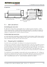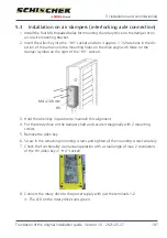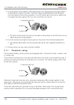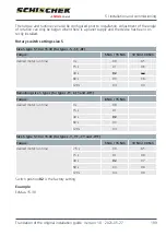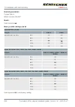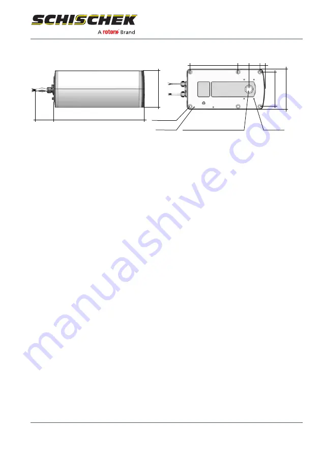
Dimensions
> 60
288
116
min. gap to drive = 60 mm
(incl. cable bend radius)
Bottom page “L”
Top page “R”
6 x Ø 8.5
2 x M4
2 x M4
125
149
176
40 40 19
Double square 16 x
16 mm
Hole prepared for self-tapping
screw M4
5.1
Axle connection
Interlocking axle connection
By default, the rotary drives are equipped with an interlocking axle connection. In other
words, the rotary drive is slotted directly onto the damper shaft. The interlocking axle con-
nection offers the most secure way to link the damper shaft and the drive as it avoids any
slipping in comparison with a friction-locked connection.
Friction-locked axle connection
A friction-locked axle connection is always required if a round damper shaft is being used. In
this case, the accessory KB-S (clamping device and rotation lock) is required. Friction-locked
axle connections are only used for size S rotary drives.
5.2
Preparing for installation
Four M4 screws are included in the delivery for mounting the rotary drives.
The drives are constructed so they are axially symmetrical. In case of a spring-return function,
the safety position must be selected on site by turning the drive through 180°. It is also im-
portant to remember that the drives have a total positioning angle of approx. 95° in order to
pre-tension the actuator (air damper or similar). Pre-tensioning is only appropriate if the
rotary drive should close the actuator. In this case, the 5° ensures the actuator is closed with
“outlet pressure”.
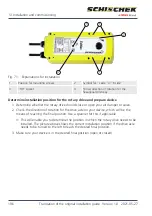
Pre-tensioning must be calibrated mechanically via the manual adjustment “HV” before the
rotary drive is mounted on the drive axle. The hexagonal Allen key must be turned anticlock-
wise if looking from the “R side” of the rotary drive, or clockwise if looking from the “L
side”. The symbol next to the “HV” socket shows the direction of rotation.
5 | Installation and commissioning
Translation of the original installation guide · Version 1.0 · 2021-05-27
195

