SI manual – Section: Operating Your SI Actuator
19
6.5 Display – Home Screen Selection
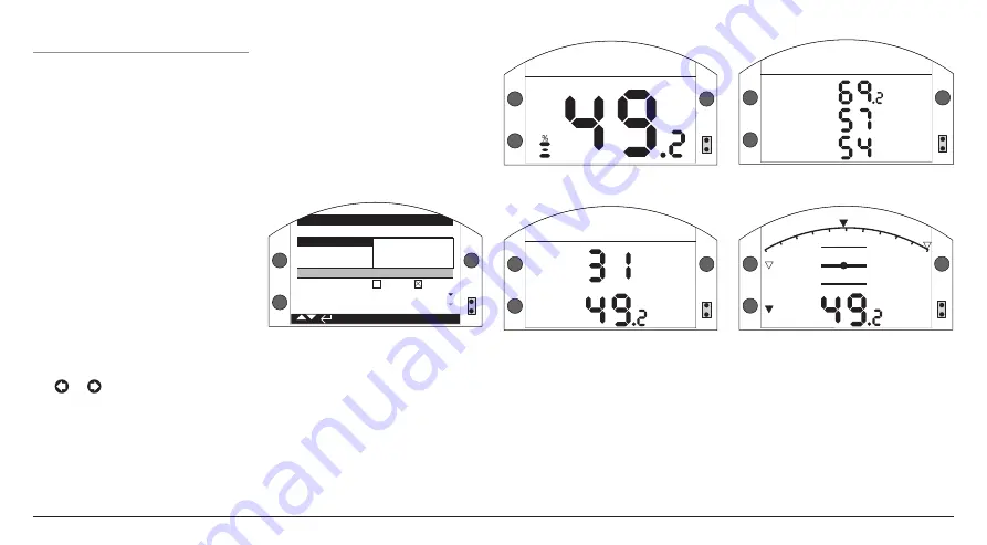
The actuator display can be set to show
any one of the following home screens:
• Digital position indication
• Analogue pressure & digital position
indication
• Digital pressure & digital position
indication
• Position & control demand
indication
The default home screen is Digital
Position indication. Home screens
indicate the live conditions measured
by the actuator.
The required home screens can be
set by the user either as a permanent
display or as a temporary display for
valve or actuator operational analysis.
Temporary Home Screen display.
Using the setting tool (refer to section
7.1) or arrow keys, scroll through
the available home screens until
the required one is displayed. The
selected screen will remain displayed
for approximately 5 minutes after the
last setting tool command or until the
actuator power is cycled.
Permanent Home Screen display.
Using the setting tool (refer to section
7.1) connect to the actuator.
From the
Settings
menu, select
Indication, Local Display
. From the
available settings, select Home Screen.
Enter the password if requested (refer
to section 7.2), select
Home screen
and from the dropdown list, select the
required Home screen for permanent
display:
R
B
R
LED INDICATION: R = RED, G = GREEN, Y = YELLOW, B = BLUE
R/G
R/G
Stopped
LCD
Home
Screen
Position
Power Save Pressure D + Pos
Contrast
Positioner
LED
Close
LED
Green
Red
Mid Travel LED On
Alarm
LED
Disabled
1/8
Y
B
Y
Fig. 6.5.1 . Home Screen Selection
Position
- Digital Position Indication
(Default)
Pressure D + Pos
- Digital pressure &
digital position indication
Positioner
- Position & control
demand indication
Once selected, the set display will be
the active, permanent home screen.
Refer to Figs 6.5.2 to 6.5.5.
R
B
R
LED INDICATION: R = RED, G = GREEN, Y = YELLOW, B = BLUE
R/G
R/G
Stopped
Y
B
Y
Fig. 6.5.2. Position
R
B
R
LED INDICATION: R = RED, G = GREEN, Y = YELLOW, B = BLUE
R/G
R/G
Pressure
Position
Stopped
Y
B
Y
Fig. 6.5.3. Pressure D + Pos
Position
Pressure Act
%
%
%
Pressure Acc
Moving Open
Low Pressure
Y
B
Y
Fig. 6.5.4 . SI4 Pressure D + Pos
R
B
R
LED INDICATION: R = RED, G = GREEN, Y = YELLOW, B = BLUE
R/G
R/G
10
90
20
80
0
100
30
70
40
60
50
Demand
Position
Y
B
Y
Fig. 6.5.5 . Positioner
Summary of Contents for Skilmatic SI 3
Page 39: ...39...


