background image

SI manual – Section: Basic Settings for Commissioning

   25

7.4  Limits

 NOTE: 

Settings and operation must 

be verified by electric operation and a 

functional test of the actuated valve.

Connect to the actuator as described 

in section 7.1. From the Position display 

home screen press the


key. The 

main menu will be displayed.

Navigate to Settings using the       

 keys and press 

 to select.

Y

Y

R

R

Fig. 7.4.1. 

The settings menu will be displayed:

Settings

Limits

Stroke Tests
Indication
Control
Security
Defaults

Navigate to Limits using the     keys 

and press 

 to select.

The setting first selected to be 

changed will require a password to 

be entered, refer to section 7.2.

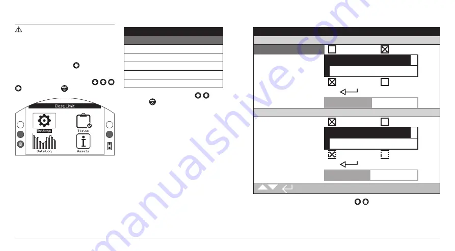
The limit settings are shown below with their factory default values:

Stopped

Close Settings

1 / 12

Action

Limit

Pressure

2 / 12

Pressure Limit

90%

3 / 12

Pressure Mid

0%

4 / 12

Semi Auto Setup

On

Off

5 / 12

Set Limit

6 / 12

Sensor Position

49%

Open Settings

7 / 12

Action

Limit

Pressure

8 / 12

Pressure Limit

90%

9 / 12

Pressure Mid

0%

10 / 12

Semi Auto Setup

On

Off

11 / 12

Set Limit

12 / 12

Sensor Position

49%


                                                                1 / 12

Function Action (1/12) is shown highlighted. Use


to scroll through functions. 

Functions will be highlighted in turn.

Summary of Contents for Skilmatic SI 3

Page 1: ...for Safe Use Installation Basic Setup and Maintenance This manual contains important safety information Please ensure it is thoroughly read and understood before installing operating or maintaining t...

Page 2: ...Selection 19 6 6 Display Status Indication Travel 20 6 7 Display Status Indication Control 20 6 8 Display Alarm Indication 20 7 Basic Settings for Commissioning________ 21 7 1 Connecting to the Actuat...

Page 3: ...e Fluid Reservoir Indication Beacon Electronics Cover Cable Entries Terminal Cover Indication Cover Display Window Fluid Fill Plug Motor Cover Actuator Hydraulic Cylinder Manifold Local Controls Handp...

Page 4: ...BTST must only be used in hazardous areas potentially explosive atmosphere permitted by the equipment classification temperature class and ambient temperature range stated in the specification this is...

Page 5: ...g Ensure the batteries are fitted with the correct polarity The battery polarity is indicated on the inside of the battery compartment of the BTST 7 The BTST contains no other user replaceable parts a...

Page 6: ...installed in Zone 1 and Zone 2 classified hazardous area locations only It should not be installed in hazardous area locations with an ignition temperature less than 135 C 275 F unless suitability fo...

Page 7: ...nameplate for unit specific details This equipment shall be installed such that the risk of impact to the window is low This equipment includes some external non metallic parts including the outer pro...

Page 8: ...led Do not store in temperatures beyond the normal operating range as stated on the data label 4 Mounting the Actuator 4 1 Lifting NOTE Refer to section 11 Weights and Measures for actuator weight Ens...

Page 9: ...Before fitting the actuator ensure that the valve is in the Fail de energised position and fit the coupling on the valve ensuring that the drive is in the correct orientation Lower the actuator on to...

Page 10: ...ing Washer Stop Nut Sealing Washer Stop Bolt Actuator Hydraulic Cylinder Adjustment Procedure Spring Canister Adjustment Remove the spring stop cap Adjust the stop bolt clockwise for reduced and anti...

Page 11: ...isconnect device for that particular actuator The actuator must be protected with a suitably rated overcurrent protection device Power supply cables must have sufficient mechanical protection properti...

Page 12: ...evenly Do not attempt to lever off the cover with a screw driver as this could damage the O ring seal and may damage the flamepath on a hazardous area certified unit Fig 5 3 1 A plastic bag in the te...

Page 13: ...opriately certified explosionproof thread adaptor or plug per entry may be used Fig 5 4 1 Remove plastic transit plugs Make cable entries appropriate to the cable type and size WARNING Ensure that thr...

Page 14: ...and the USA require mains supply cables to comply with CSA C22 2 No 21 or ANSI UL 817 WARNING SI Wiring can reach 81 C 178 F in a 70 C 158 F ambient temperature WARNING Refer to figure 5 1 1 for term...

Page 15: ...ymbols indicate operating mode Electrical Operation Manual Operation Pump to Open Manual Operation Pump to Close Stop The default position normally closed or normally open is determined by the actuato...

Page 16: ...ly be replenished electrically Stayput With Accumulator Manually operate the actuator using stored energy from the accumulator Pull the manual override handle outwards and rotate to select Manual Oper...

Page 17: ...this allows the remote control signals to operate the actuator Select Stop by turning the red selector 90 anti clockwise 6 3 Accumulator Optional The accumulator for spring return actuators is used to...

Page 18: ...n in the text in the line above the main display 7 Infrared Icon This icon flashes during setting tool communication activity LEDs will also flash when keys are pressed 8 Percentage Open Icon When a n...

Page 19: ...actuator From the Settings menu select Indication Local Display From the available settings select Home Screen Enter the password if requested refer to section 7 2 select Home screen and from the drop...

Page 20: ...dication and is displayed for approximately 2 seconds after the control mode or signal is applied Figure 6 7 1 shows the control status example Remote Control Y Y R R Fig 6 7 1 6 8 Display Alarm Indic...

Page 21: ...ings have been made and checked The basic settings affect the correct operation of the valve by the actuator If the actuator has been supplied with the valve the valvemaker or supplier may have alread...

Page 22: ...a period of 6 minutes with no key commands Bluetooth connection will be turned off and the BTST and display blue lights will go out To manually turn off Bluetooth connection at any time press the set...

Page 23: ...B BLUE Y Y R G R G CloseLimit CloseSettings Action Limit Pressure PressureLimit 90 PressureMid 0 SemiAutoSetup On Off SetLimit SensorPosition 15 OpenSettings 1 12 Y B Y R R Fig 7 2 4 If the user does...

Page 24: ...Semi Auto Setup Set Limit Sensor Position Open Settings Action Pressure Limit Pressure Mid Semi Auto Setup Set Limit Sensor Position Full Stroke Setup Test Result Last Test Full Stroke Times Secs Ope...

Page 25: ...ecurity Defaults Navigate to Limits using the keys and press to select The setting first selected to be changed will require a password to be entered refer to section 7 2 The limit settings are shown...

Page 26: ...Mid value is set at the same as the Pressure Limit When set between 1 to 100 the Pressure Mid value is a proportion of the maximum system pressure WARNING If the actuator fails to complete a close or...

Page 27: ...t is powered by the stored energy in the spring the operating time is known as the spring speed Control can also be optionally configured in the movement direction powered by the hydraulic pump accumu...

Page 28: ...he full stroke times recorded Open Limit Full Stroke 1 13 Setup 2 13 Test 3 13 Result Last test Pass Full Stroke Times Secs 4 13 Open Setup 37 67 5 13 Open Min 30 13 6 13 Open Max 45 20 7 13 Open Last...

Page 29: ...ESD Min this time can be adjusted and is used to determine a pass or fail By default it is set to be the ESD Setup time less 10 10 13 ESD Max this time can be adjusted and is used to determine a pass...

Page 30: ...position set in 1 8 and then back again The actuator will display the following Instruction when this is used Partial Stroke Test will be run Ok to proceed 4 8 Results Last Test The result from the p...

Page 31: ...erforming Setup Press to select the setup function 2 7 Test Test will discharge all pressurised fluid in the accumulator and then replenish pressure in the accumulator to the Accumulator Set Pressure...

Page 32: ...the Limit Switches The limit switches are stacked next to the indication shaft Attached to the shaft are the limit switch cams The switches can be triggered at different points through the actuator mo...

Page 33: ...roperly lubricated Check the control module enclosure for external damage loose or missing fasteners All external fasteners must be tightened to 40 Nm 30 lbf ft Ensure there is not an excessive build...

Page 34: ...e reservoir Ensure that the fluid is cleaned through a 3 micron filter as it is added into the reservoir this will reduce the chance of contamination When conducting a complete fluid change the system...

Page 35: ...ssis mezzanine cover No No 17 02 04 Disposal as general commercial waste Polycarbonate Indication beacon No Yes 17 02 03 Use licensed recyclers Hydraulic Fluid Mineral Standard Actuator Yes Yes 13 02...

Page 36: ...ctuators Due to the contract specific nature of SI4 equipment please refer to contract documentation for details of weights and volume of hydraulic fluid 12 Vibration Shock and Noise Standard SI range...

Page 37: ...European Hazardous Area ATEX 2014 34 EU EN 60079 0 EN 60079 1 EN 60079 7 EN ISO 80079 36 EN ISO 80079 37 II 2G Ex db h IIB T4 Gb Ex db h IIC T4 Gb T ambient to International Hazardous Area IECEx IEC6...

Page 38: ...T4 Gb Ex db IIC T4 Gb T ambient to USA Class I Zone 1 AEx db IIB T4 Gb Class I Zone 1 AEx db IIC T4 Gb T ambient to eb added on versions with increased safety terminal enclosure Down to 40 C 40 F Up...

Page 39: ...39...

Page 40: ...e visit our website at www rotork com The name Rotork is a registered trademark Rotork recognises all registered trademarks The Bluetooth word mark and logos are registered trademarks owned by Bluetoo...

Reviews: