32
SI manual – Section: Setting the Indication Switches (Optional)
8. Setting the Indication
Switches (Optional)
The SI can be fitted with up to four
internal indication switches which can
be used to monitor the position of
the actuator. These are accessed by
removing the indication cover.
WARNING:
Ensure all power
supplies are isolated before removing
the indication cover.
8.1 Removing the Indication Cover
Using a 6 mm Allen (hex.) key, loosen
the four captive screws evenly. Do not
attempt to lever off the cover with
a screw driver as this could damage
the O-ring seal and may damage the
flamepath on a certified unit.
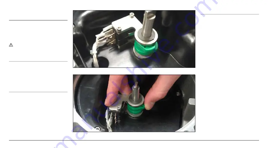
8.2 Adjusting the Limit Switches
The limit switches are stacked next to
the indication shaft. Attached to the
shaft are the limit switch cams. The
switches can be triggered at different
points through the actuator movement
by adjusting the offset angle on
the cams. The cams are adjusted by
moving them away from their seat and
then rotating them into the desired
positon. Once released the spring will
push the cam back into its seat.
Fig. 8.2.1.
Fig. 8.2.2 .
8.3 Replacing the Indication Cover
Ensure the cover O-ring seal and spigot
joint are in good condition and lightly
greased before refitting cover. Check
that the shaft coupling groove on the
underside of the cover is aligned with
the indication shaft slot. Carefully
place the cover back on as straight
as possible and press down until it is
fully engaged. Tighten all four screws
evenly.
Summary of Contents for Skilmatic SI 3
Page 39: ...39...


