Disconnect the plug from the
power source before making
any assembly, adjustments or changing
accessories. Such preventive safety measures
reduce the risk of starting the tool accidentally.
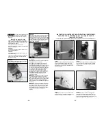
STEP 1: INSTALLING ZIP® BITS
The Zip Bits are held by a collet system. At the
time your tool was assembled, the 1/8" collet (used
for 1/8" Zip Bits) was installed for your convenience.
The 1/4" collet (used for 1/4" Zip Bits) is located in
the Zip Bit package with your tool.
Only use Roto Zip Tool Corporation Zip Bits
with your Spiral Saw power tool.
Identify the different parts of your Zip Bits.
The Zip Bit flutes are sharp and
should be handled with caution.
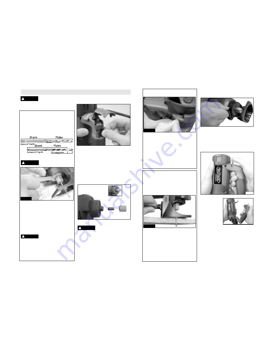
To insert a Zip Bit into the tool, first remove the
standard equipment wrench and locate the
shaft lock button. Depress and hold down the
shaft lock button with one hand and at the same
time loosen the collet nut with the other hand by
turning it counter clockwise with the wrench for
a couple rotations. Remove the old Zip Bit (if
there is one), insert shank of Zip Bit into the
collet so that 1/16" to 1/8" of smooth shank
remains visible above the collet.
Do not allow the flutes/cutting
edges of the Zip Bit to fall into
the collet, and do not tighten the collet around the
flutes; doing so will result in decreased Zip Bit life.
After properly placing the Zip Bit into the collet,
depress the shaft lock button and simultaneously
tighten the collet nut in a clockwise direction, first
by hand, and then with the wrench until Zip Bit is
held securely.
Collet and Zip Bit storage compartment
area located in the handle
Changing the Collet
As stated above, the 1/8" collet is used with 1/8"
diameter Zip Bits and the 1/4" collet is used with
1/4" diameter Zip Bits. To interchange collets,
first remove the Zip Bit. Continue to loosen and
unscrew the collet nut until you can remove it
from the tool. Remove the collet and replace it
with another. (Each collet is double-ended, and
either end is acceptable to use.) By hand,
re-tighten the collet nut around the collet in a
clockwise direction. You are now ready to insert a
new Zip Bit as instructed in step 1 above.
DURING STORAGE of your
tool when there is no Zip Bit
in the collet, DO NOT tighten the collet nut
down onto an empty collet. Doing so will make
the collet hole smaller, preventing you from
inserting Zip Bits into it in the future.
-7-
-6-
Operating Instructions
!
WARNING
SYSTEM COMPLETE
SYSTEM SEPERATED
COLLET
NUT
COLLET
!
CAUTION
!
CAUTION
!
WARNING
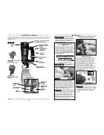
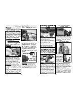
STEP 2: ADJUSTING THE AIR
DIVERTER
Always make sure tool is OFF ("0" position)
before making any adjustments to the air
diverter vents.
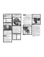
The exhaust air diverter vent redirects cooling
air toward the base plate to help remove debris
that may gather in the base plate while cutting.
To open the diverter vent so air pushes towards
the cutting surface, slide the air diverter lever
toward the handle. To close the vent, slide the
lever away from the handle.
STEP 3: ADJUSTING THE DEPTH
GUIDE BEFORE MAKING A CUT
The Revolution is designed to cut materials up
to 1” thick. Use the depth guide to adjust the
depth of the cut. The depth guide assembly
consists of the depth guide & locking lever, and
the adjustable base plate & locking screw.
Locate the base plate and its locking screw.
Using the end of the standard wrench, loosen
(counter clockwise) the screw enough to enable
the base plate to slide up or down to the desired
depth of cut. For best performance, set the base
plate so the Zip Bit protrudes approximately 1/8"
beyond the material being cut. For example, to
cut a piece of 1/2" thick plywood, set the base
plate so the Zip Bit protrudes 5/8" below the
base plate, as shown here. Re-tighten the screw
in a clockwise direction.
Removing Depth Guide Assembly From Tool
and Reinstalling
In order to remove the depth guide from the
tool, release the locking lever and pull the entire
assembly straight off of the tool. To reattach
the assembly, fully replace the guide onto the
tool collar and lock the clamp lever.
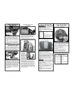
Removing and Replacing the Handle
Turn the tool OFF
and unplug it.
Firmly grasp the
tool. Slide open
the cam lock lever
to the unlock
position. Gently
lift-up the rear end
of the handle and
the cam lock pin will
disengage from the
tool. Continue to gently lift-up the handle and
the 2 latches at the front of the handle will also
disengaged. Remove handle from tool.You can
only operate the tool in the "2" ON position
while the handle is disengaged from the tool.
To replace the handle, reverse the steps above.
Gently engage the 2 front latches into the tool,
slide the cam lock pin into the open hole. Gently
pull handle to check that both ends are secured
before using.
Step 2
Step 3
Step 1

