background image

Disconnect the plug from the power source
and/or the battery pack from the power tool
before  making  any  adjustments,  changing
accessories,  or  storing  power  tools.  
Such
preventive safety measures reduce the risk of
starting the power tool accidentally.

Store  idle  power  tools  out  of  the  reach  of
children and do not allow persons unfamiliar
with the power tool or these instructions to
operate  the  power  tool.  
Power  tools  are
dangerous in the hands of untrained users.

Maintain power tools. Check for misalignment
or  binding  of  moving  parts,  breakage  of
parts  and  any  other  condition  that  may
affect the power tool’s operation. If damaged,
have  the  power  tool  repaired  before  use.
Many  accidents  are  caused  by  poorly
maintained power tools.

Keep cutting tools sharp and clean. Properly
maintained  cutting  tools  with  sharp  cutting
edges are less likely to bind and are easier to
control.

Use  the  power  tool,  accessories  and  tool
bits etc. in accordance with these instructions,
taking into account the working conditions
and  the  work  to  be  performed.  
Use  of  the
power  tool  for  operations  different  from  those
intended could result in a hazardous situation.

Service

Have your power tool serviced by a qualified
repair  person  using  only  identical
replacement  parts.  
This  will  ensure  that  the
safety of the power tool is maintained.

-3-

Safety Warnings Common for Grinding,

Sanding, Wire Brushing, and Abrasive

Cutting-Off Operations:

This power tool is intended to function as a
grinder,  sander,  or  cut-off  tool.  Read  all
safety  warnings,  instructions,  illustrations
and specifications provided with this power
tool.  
Failure  to  follow  all  instructions  listed
below  may  result  in  electric  shock,  fire  and/or
serious injury.

Operations  such  as  wire  brushing  or
polishing  are  not  recommended  to  be
performed  with  this  power  tool. 
Operations
for which the power tool was not designed may
create a hazard and cause personal injury.

Do  not  use  accessories  which  are  not
specifically designed and recommended by
the  tool  manufacturer.  
Just  because  the
accessory can be attached to your power tool,
it does not assure safe operation.

The  rated  speed  of  the  accessory  must  be
at  least  equal  to  the  maximum  speed
marked  on  the  power  tool.  
Accessories
running  faster  than  their  RATED  SPEED  can
break and fly apart.

The  outside  diameter  and  the  thickness  of
your accessory must be within the capacity
rating  of  your  power  tool.  
Incorrectly  sized
accessories  cannot  be  adequately  guarded  or
controlled.

The  arbor  size  of  wheels,  flanges,  backing
pads or any other accessory must properly
fit the spindle of the power tool. 
Accessories
with  arbor  holes  that  do  not  match  the
mounting  hardware  of  the  power  tool  will  run
out  of  balance,  vibrate  excessively  and  may
cause loss of control.

Do  not  use  a  damaged  accessory.  Before
each  use  inspect  the  accessory  such  as
abrasive  wheels  for  chips  and  cracks,
backing pad for cracks, tear or excess wear,
wire  brush  for  loose  or  cracked  wires.  If
power tool or accessory is dropped, inspect
for  damage  or  install  an  undamaged
accessory.    After  inspecting  and  installing
an  accessory,  position  yourself  and
bystanders  away  from  the  plane  of  the
rotating  accessory  and  run  the  power  tool
at maximum no-load speed for one minute.
Damaged accessories will normally break apart
during this test time.

Wear  personal  protective  equipment.
Depending  on  application,  use  face  shield,
safety  goggles  or  safety  glasses.  As
appropriate,  wear  dust  mask,  hearing
protectors,  gloves  and  workshop  apron
capable  of  stopping  small  abrasive  or
workpiece  fragments.  The  eye  protection
must  be  capable  of  stopping  flying  debris
generated  by  various  operations. 
The  eye
protection  must  be  capable  of  stopping  flying

Power Tool-Specific Safety Warnings

RZ 2610021432 10-12_RZ 2610021432 10-12.qxp  10/30/12  9:57 AM  Page 3

Summary of Contents for SS560VSC

Page 1: ...nnement s curit Instrucciones de funcionamiento y seguridad 1 877 ROTOZIP 1 877 768 6947 www rotozip com Call Toll Free for Consumer Information Service Locations Pour obtenir des informations et les...

Page 2: ...nal protective equipment Always wear eye protection Protective equipment such as dust mask non skid safety shoes hard hat or hearing protection used for appropriate conditions will reduce personal inj...

Page 3: ...ower tool Operations for which the power tool was not designed may create a hazard and cause personal injury Do not use accessories which are not specifically designed and recommended by the tool manu...

Page 4: ...the wheel that is entering into the pinch point can dig into the surface of the material causing the wheel to climb out or kickout The wheel may either jump toward or away from the operator depending...

Page 5: ...t be placed under the workpiece near the line of cut and near the edge of the workpiece on both sides of the wheel Use extra caution when making a pocket cut into existing walls or other blind areas T...

Page 6: ...ng the bit to break Never touch the bit during or immediately after the use After use the bit is too hot to be touched by bare hands Never lay the tool down until the motor has come to a complete stan...

Page 7: ...maximum safe operating speed greater than the no load RPM marked on the attachment Wheels running over the rated speed can fly apart and cause injury Before each use inspect the cut off wheel for chip...

Page 8: ...entify the fire forward and reverse fire positions The attachment is in the fire forward position when the directional arrow points toward the operator and it is in the reverse fire position when the...

Page 9: ...carbon tetrachloride ammonia etc may damage plastic parts Risk of injury to user The power cord must only be serviced by a Rotozip Factory Service Center or Authorized Rotozip Service Station Some du...

Page 10: ...ue 1 2 3 Selector settings Speed torque or position settings I II III Higher number means greater speed Infinitely variable selector with off Speed is increasing from 0 setting Arrow Action in the dir...

Page 11: ...that this tool is listed by the Intertek Testing Services to United States and Canadian Standards Symbols continued IMPORTANT Some of the following symbols may be used on your tool Please study them...

Page 12: ...isk of starting the tool accidentally WARNING NOTE For tool specifications refer to nameplate on your tool Spiral Saw INTAKE AIR VENTS EXHAUST AIR VENTS SLIDE ON OFF SWITCH WITH LOCK SUPPORT STRAP WRE...

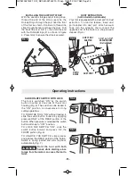
Page 13: ...t damage to tool never use the shaft lock as a braking devise to stop the tool from rotating Use the standard equipment wrench to loosen nut counter clockwise Fig 2 Remove the old bit if there is one...

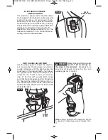
Page 14: ...arting since torque from the motor can cause the tool to twist INSTALLING THE SUPPORT STRAP With the wrench storage pocket facing down thread the end of the strap opposite the Rotozip logo through the...

Page 15: ...e edge of the material Be ready for a potential kickback where the tool can suddenly get out of control Note always adjust the bit depth as shown in figure 9 and plunge cut per figures 10 11 1 8 THUMB...

Page 16: ...xture or opening which has live electrical wires or any wall which may have live electrical wiring behind it as the bit could conduct current to the tool creating an electrocution hazard for the opera...

Page 17: ...edge of the box Fig 13 Step 3 Pull the bit out far enough to slip it over the edge of the box so it is now against the outside of the box Fig 14 Step 4 While keeping the bit in contact with the outsi...

Page 18: ...Abrasive Cut Off attachment Functional Description and Specifications Zipmate attachment must be used only with an hard auxiliary control side handle Two handed control of solid gripping handles will...

Page 19: ...in and rotate the collet nut and shaft until the shaft lock engages and holds the shaft 2 Remove the collet nut by rotating it counter clockwise Remove the collet from the tool shaft 3 Position the at...

Page 20: ...UTER WASHER Fig 8 If the shaft moves while attempting to loosen the lock bolt press the spindle lock Fig 8 2 Slide wheel behind the guard face and mount it against the INNER WASHER on the shaft Fig 6...

Page 21: ...wheel 5 Keep guard covering between wheel and user 6 Make sure the guard lock lever is in the closed position and the guard is securely mounted to the attachment Use the allen wrench to adjust the gu...

Page 22: ...add to the thickness of the finished floor Also note that this saw will create a cut approximately 3 4 deep This saw creates a cut approximately 3 16 above the surface where the guard is resting When...

Page 23: ...t the tool from the power supply before cleaning or performing any maintenance The tool may be cleaned most effectively with compressed dry air Always wear safety goggles when cleaning tools with comp...

Page 24: ...rpose XBITS XB MP Multipurpose Dust Management XBITS XB MPDM Floor Tile XBITS XB FT Floor Tile XBITS XB FTH Floor Tile and Countertop XBITS XB FTC Wall Tile XBITS XB TC Grout Removal XBITS XB GR Under...

Page 25: ...faites pour l ext rieur et r duisent le risque de choc lectrique S il est absolument n cessaire d utiliser l outil lectroportatif dans un endroit humide utilisez une alimentation prot g e par un disjo...

Page 26: ...uleuse une ponceuse ou un outil de tron onnage Veuillez lire toute la documentation relative la s curit qui a t fournie avec cet outil lectroportatif notamment les avertissements les consignes les ill...

Page 27: ...mat riaux inflammables Des tincelles pourraient enflammer ces mat riaux N utilisez pas d accessoires qui exigent des liquides de refroidissement L utilisation d eau ou d autres liquides de refroidisse...

Page 28: ...ison quelconque mettez l outil lectroportatif l arr t et tenez le sans bouger jusqu ce que la meule s arr te compl tement N essayez jamais de retirer la meule de tron onnage au milieu d une coupe tant...

Page 29: ...toujours pousser l embout dans le mat riau dans le m me sens que celui du bord tranchant qui quitte le mat riau Avec l outil vu du dessus l embout tourne en sens horaire Si l outil se trouve entre vo...

Page 30: ...ozip peut aussi servir de poign e Assurez vous toujours que le capot de meule et la poign e auxiliaire ont t remont s et fermement fix s sur Zipmate s quand vous changez de sens de rotation pour passe...

Page 31: ...ces mat riaux Il ne faut jamais couper ou tenter de couper du magn sium avec cet accessoire La poussi re produite durant la coupe de magn sium est tr s inflammable et peut tre explosive dans certaine...

Page 32: ...e agr e de Rotozip Les travaux la machine tel que pon age sciage meulage per age et autres travaux du b timent peuvent cr er des poussi res contenant des produits chimiques qui sont des causes reconnu...

Page 33: ...vitesse de couple ou de position Un l ll lll nombre plus lev signifie une vitesse plus grande S lecteur variable l infini avec arr t La vitesse augmente depuis le r glage 0 Fl che Action dans la direc...

Page 34: ...est approuv par Intertek Testing Services selon les normes des tats Unis et du Canada Symboles suite IMPORTANT Certains des symboles suivants peuvent tre utilis s sur votre outil Veuillez les tudier e...

Page 35: ...MARQUE Pour sp cifications de l outil reportez vous la plaque signal tique de votre outil AVERTISSEMENT Spiral Saw 35 VENTS D AIR D ADMISSION VENTS D AIR D CHAPPEMENT INTERRUPTEUR MARCHE ARR T COULISS...

Page 36: ...de 5 32 po 0 156 po Pour changer le douille commencer par retirer l embout Continuer ensuite de d visser l crou de douille jusqu ce qu il se d tache de l appareil Retirer le douille et le remplacer p...

Page 37: ...ire tordre l outil Consignes de fonctionnement 37 INSTALLATION DE LA COURROIE DE PR HENSION En orientant la poche de rangement de la cl vers le bas faites passer le bout de la courroie du c t oppos du...

Page 38: ...e jusqu ce que le guide de profondeur puisse glisser librement jusqu la profondeur de coupe souhait e environ 1 8 po de plus que l paisseur du mat riau et resserrez la vis de blocage en tournant en se...

Page 39: ...t assurerait la conduction du courant vers l appareil et mettrait l utilisateur risque de subir un choc lectrique Couper le courant alimentant ces fils l aide des fusibles ou des disjoncteurs Toujours...

Page 40: ...u bo tier de telle sorte qu elle soit en contact avec l ext rieur du bo tier Fig 14 tape 4 tout en maintenant l embout en contact avec l ext rieur du bo tier d placez l outil dans le sens antihoraire...

Page 41: ...ite dans un rapport de 211 1 quand vous utilisez l accessoire de tron onnage meule Accessoire de tron onnage meule Zipmate AVERTISSEMENT 41 L accessoire Zipmate ne peut tre utilis qu avec une poign e...

Page 42: ...e 2 Retirez l crou de douille en le faisant tourner dans le sens inverse des aiguilles d une montre Retirez la douille de l arbre de l outil 3 Placez l accessoire sur le point de contact filet Rotozip...

Page 43: ...ur coupe ras si vous ne voulez pas effectuer une coupe ras Le mod le ZM4 ne comporte pas de dispositif de protection appropri pour r aliser des coupes droites avec des meules con ues pour des coupes r...

Page 44: ...ment le m canisme de blocage Contr lez le serrage du levier apr s chaque tour complet donn la vis de r glage Pour viter que l outil ne rebondisse ou qu il soit ab m il faut toujours s assurer que les...

Page 45: ...es mat riaux pour obtenir l paisseur totale du plancher fini Notez aussi que cette meule produira une coupe d environ 3 4 po de profondeur Cette meule produit une coupe approximativement 3 16 po au de...

Page 46: ...il faut toujours d brancher l outil avant de le nettoyer ou de l entretenir Le meilleur moyen de nettoyer l outil est d utiliser de l air comprim sec Il faut toujours porter des lunettes de protection...

Page 47: ...aux de sol XB FTH Embout XBITS pour carreaux de sol et comptoirs XB FTC Embout XBITS pour carreaux de rev tement XB TC Embout XBITS pour l limination du coulis de ciment XB GR Embout XBITS pour sous f...

Page 48: ...uso a la intemperie reduce el riesgo de que se produzcan sacudidas el ctricas Si es inevitable utilizar una herramienta mec nica en un lugar h medo utilice una fuente de energ a protegida por un inter...

Page 49: ...ca Si no se siguen todas las instrucciones que se indican a continuaci n el resultado podr a ser descargas el ctricas incendio y o lesiones graves No se recomienda realizar operaciones tales como cepi...

Page 50: ...o que gira lo cual a su vez hace que la herramienta mec nica descontrolada sea forzada en sentido opuesto al de rotaci n del accesorio en el punto del atoramiento Por ejemplo si la pieza de trabajo en...

Page 51: ...o y retroceso de la rueda Las piezas de trabajo grandes tienden a combarse bajo su propio peso Se deben colocar soportes debajo de la pieza de trabajo cerca de la l nea de corte y cerca del borde de l...

Page 52: ...nca toque la broca durante ni inmediatamente despu s de la utilizaci n Despu s del uso la broca est demasiado caliente como para tocarla con las manos desnudas Nunca deje la herramienta hasta que el m...

Page 53: ...la torniller a de montaje de la herramienta funcionar n exc ntricamente vibrar n excesivamente y causar n p rdida de control No amuele en el lado de ruedas abrasivas de corte de tipo 1 Las fuerzas lat...

Page 54: ...cha de sentido de rotaci n ubicada en el lado trasero del protector se puede utilizar para identificar las posiciones de disparo de avance y disparo inverso El aditamento est en la posici n de disparo...

Page 55: ...ridad podr an montarse incorrectamente Ciertos agentes de limpieza tales como gasolina tetracloruro de carbono amon aco etc podr an da ar las piezas de pl stico Riesgo de lesiones para el usuario El c...

Page 56: ...e velocidad par motor o posici n I II III Un n mero m s alto significa mayor velocidad Selector infinitamente variable La velocidad aumenta desde la graduaci n de 0 con apagado Flecha Acci n en la dir...

Page 57: ...ices ha catalogado esta herramienta indicando que cumple con las normas estadounidenses y canadienses S mbolos continuaci n IMPORTANTE Es posible que algunos de los s mbolos siguientes se usen en su h...

Page 58: ...nsulte la placa del fabricante colocada en la herramienta ADVERTENCIA Spiral Saw 58 ORIFICIOS DE ENTRADA DE AIRE ORIFICIOS DE SALIDA DE AIRE INTERRUPTOR CORREDIZO DE ENCENDIDO Y APAGADO CON CIERRE COR...

Page 59: ...unca use el cierre del eje como dispositivo de frenado para hacer que la herramienta deje de girar Utilice la llave de tuerca del equipo est ndar para aflojar la tuerca en sentido contrario al de las...

Page 60: ...cer que la herramienta se tuerza INSTALACI N DE LA CORREA DE SOPORTE Con el bolsillo de almacenamiento de la llave de tuerca orientado hacia abajo inserte el extremo de la correa opuesto al logotipo R...

Page 61: ...etroceso potencial con el cual se puede perder repentinamente el control de la herramienta Nota Ajuste siempre la profundidad de la broca de la manera que se muestra en la figura 9 y corte por inmersi...

Page 62: ...bles el ctricos vivos o en una pared que pueda esconder cables el ctricos ya que la broca puede conducir la corriente a la herramienta y representar un riesgo de electrocuci n del operador Apague los...

Page 63: ...e la broca lo suficiente como para deslizarla sobre el borde de la caja de manera que ahora la broca se encuentre contra la parte exterior de la caja Fig 14 Paso 4 Al mismo tiempo que mantiene la broc...

Page 64: ...aje o ajuste o cambiar accesorios Estas medidas de seguridad preventivas reducen el riesgo de arrancar la herramienta accidentalmente NO INCLUIDO CON TODOS LOS JUEGOS Nota La velocidad de su herramien...

Page 65: ...y el eje hasta que el cierre del eje se acople y mantenga sujeto el eje 2 Retire la tuerca del portaherramienta gir ndola en sentido contrario al de las agujas del reloj Retire el portaherramienta del...

Page 66: ...je se mueve mientras se intenta aflojar el perno de fijaci n presione el cierre del husillo Fig 8 2 Deslice la rueda detr s de la cara del protector y m ntela contra la ARANDELA INTERIOR en el eje Fig...

Page 67: ...eda 5 Mantenga la cubierta del protector entre la rueda y el usuario 6 Aseg rese de que la palanca de fijaci n del protector est en la posici n cerrada y de que el protector est montado de modo seguro...

Page 68: ...aproximadamente 3 4 de pulgada de profundidad Esta sierra crea un corte aproximadamente 3 16 de pulgada por encima de la superficie sobre la cual se apoya el protector Cuando se corten jambas de puer...

Page 69: ...La lubricaci n aplicada en la f brica dura toda la vida til de la herramienta ESCOBILLAS DE CARB N Las escobillas y el conmutador de la herramienta han sido dise ados para muchas horas de servicio fia...

Page 70: ...B FTH Brocas XBITS para baldosa de piso y tablero de mostrador XB FTC Brocas XBITS para baldosa de pared XB TC Brocas XBITS quitalechada XB GR Brocas XBITS para bases de piso XB UL Brocas XBITS para y...

Page 71: ...71 Notes Remarques Notas RZ 2610021432 10 12_RZ 2610021432 10 12 qxp 10 30 12 9 58 AM Page 71...

Page 72: ...TRE TENU POUR RESPONSABLE DES INCIDENTS OU DOMMAGES INDIRECTS INCLUANT MAIS NE SE LIMITANT PAS AUX PERTES DE PROFITS CONS CUTIFS LA VENTE OU L USAGE DE CE PRODUIT CERTAINS TATS AM RICAINS ET CERTAINE...

Reviews: