RMS-LOG Wireless / LAN Data Loggers
E-M-RMS-MLOG-868-V1_0.docx
Instruction Manual
1.2 Device Overview
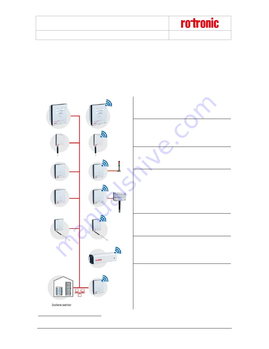
All devices can be configured as wanted as modules of the system. The following table shows all basic types of
the RMS devices. Almost all modules
have the following options:
•
Interface: Ethernet / Wireless
•
Housing: Wall housing / DIN top hat rail housing
Display Module
The display module can show any values from the
RMS network. Humidity, temperature and switch
states can be configured per software.
Standard Logger
Records the measured data of the digital HygroClip
HCD or other RMS probes. Stored in the ring
memory, the data are then sent to the server
software.
Output Module
Provides two analog voltage or current outputs or is
also available as variant with two solid-state relays in
order, for example, to switch alarm lamps.
Input Module
Records voltage or current signals from analog
devices such as particle counters, flow transmitters
or CO2 probes. For example:
•
HF5 transmitter (humidity & temperature)
•
AF1 transmitter (air flow)
•
CO2 transmitter (CO2)
•
PF4 transmitter (differential pressure)
Temperature Logger
The loggers can be equipped with various
temperature sensors (NTC, Pt100, Pt1000 or K-
element). This offers the highest flexibility in use.
Mini Logger
A temperature logger with integrated or remote NTC
sensor. Instead of a temperature sensor, it is also
available with a switch input in order, for example, to
monitor door contacts.
Gateway
The gateway is the connecting element between
Ethernet and wireless networks and forwards the
data flow from the loggers to the data centre.
1
Except for the Mini Logger
© 2016
ROTRONIC AG
Bassersdorf
Switzerland
Page 4 of 22


